
What is The Machining Process for Shaft Part?
Machining shafts is tricky. A single error can scrap the part, wasting money. Understanding the process from roughing to finishing is the key to getting it right every time.
The **shaft machining process** involves turning, milling, grinding, and heat treatment. It starts with rough turning to get the basic shape, followed by heat treatment for hardness. Then, semi-finishing and finish turning create precise dimensions. Grinding achieves the final surface finish and accuracy.
The general process gives us a good roadmap. But the real magic is in the details. Different shafts, like a lathe spindle or a long, slender wheel shaft, have their own unique steps and challenges. Let's look at a few specific examples to see how the process changes. This will help you understand the small details that make a big difference in quality.
一. Machining Process of CA6140 Horizontal Lathe Spindle
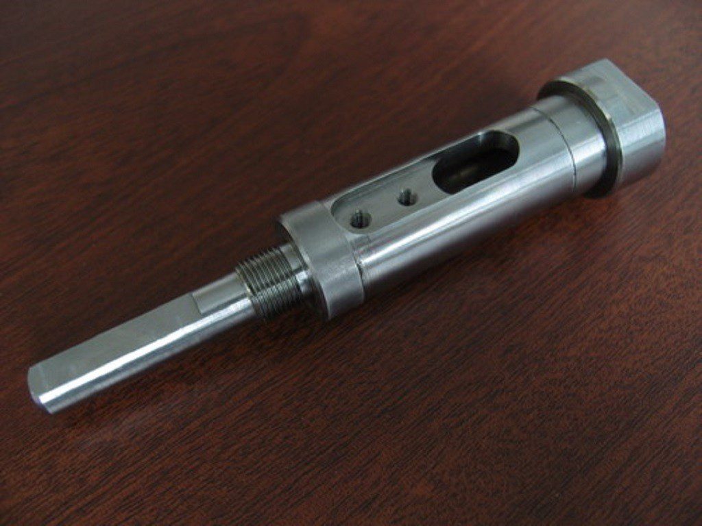
The **spindle**, the primary rotating component in metal-cutting machine tools, stands as the most representative shaft part. It typically features internal and external cylindrical surfaces, conical surfaces, along with various geometric features including threads, keyways, spline grooves, transverse holes, grooves, and flanges. Given its stringent precision requirements and complex machining challenges, proper analysis and resolution of critical aspects like datum selection and process planning can effectively streamline the production of other shaft components. This section demonstrates machining processes for shaft parts using the CA6140 horizontal lathe spindle as a case study. The CA6140 lathe spindle is fabricated from **45# steel**.
1. Analysis of spindle function and technical requirements
The spindle, a critical component of a lathe, connects directly to fixtures (such as chucks or centers) at its front end to secure and rotate workpieces during surface forming operations. To ensure machining accuracy, the spindle must achieve exceptional rotational precision while withstanding bending moments and torque during operation. It also requires sufficient rigidity, wear resistance, and vibration damping capabilities. Consequently, the spindle's manufacturing quality significantly impacts the machine's operational precision. Therefore, the technical specifications for spindles encompass the following aspects:
Support journal.
The two support journals A and B of the main shaft are fitted with the inner bore of corresponding bearings, serving as the assembly reference for the main shaft assembly. Their manufacturing precision directly affects the rotational accuracy of the assembly. When the support journals are misaligned, radial runout occurs in the main shaft, which compromises the machining quality of workpieces during lathe operation. Therefore, stringent requirements are imposed on the support journals. **Dimensional specifications**: manufactured to T5 grade standards, with roundness tolerances of 0.005mm and radial runout tolerances of 0.005mm for both journals, along with surface roughness Rα.
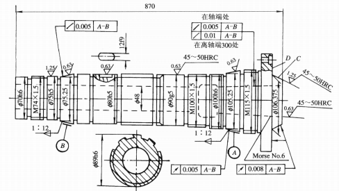
Figure 6-1-30: Schematic Diagram of the Spindle of CA6140 Horizontal Lathe
Clamping Surface.
The tapered hole at the spindle's front end is a **Morse taper** designed for installing centers or mandrels. Its centerline must be precisely coaxial with the support journal's centerline to prevent roundness and coaxiality errors in the workpiece. The contact area of the spindle's tapered surface must exceed 75%. The permissible circular runout tolerance for the tapered hole relative to support journals A and B is **0.005mm** near the shaft end and **0.01mm 300mm** from the shaft end. The surface roughness Rα value must be 0.4μm.
The front end of the spindle features a short conical surface serving as the centering surface for the chuck installation. To ensure precise centering accuracy, this conical surface must be coaxial with the support journal, while its end face must be perpendicular to the spindle's rotational axis. The allowable circular runout tolerance for the conical surface relative to support journals A and B is **0.008mm**, with equivalent tolerances for end face runout relative to the journals' centers. The surface roughness Rα value is maintained at 0.8μm.
Thread Surface.
The thread surface of the spindle serves as the mating surface for the locking nut. When the centerline of the thread surface deviates from the centerline of the support journal, it causes the end face runout of the locking nut in the spindle assembly. This results in the centerline of the inner ring of the rolling bearing tilting, leading to radial runout of the spindle. Therefore, during thread surface machining, it is essential to maintain **coaxiality** between the thread centerline and the support journal centerline.
Axial positioning surface.
The axial positioning surface of the spindle should be perpendicular to the rotation axis of the spindle. Otherwise, the spindle will move axially periodically, which will affect the end face flatness of the workpiece being processed, and cause pitch error when machining threads.
Other technical requirements.
In order to improve the comprehensive mechanical properties of parts, in addition to the above processing requirements for each surface, there are also requirements for material selection, heat treatment, etc.
2. The machining process of the spindle
After analyzing the structural features and technical requirements of the spindle, the machining process is determined based on production batch size, equipment conditions, and the processing characteristics of shaft components. **Table 6-1-10** illustrates the machining process for the spindle in single-piece or small-batch production.
Table 6-1-10: Machining Process of CA6140 Horizontal Lathe Spindle
| Serial number | Process content | Positioning reference | equipment |
|---|---|---|---|
| 1 | hammer forging | ||
| 2 | normalization | ||
| 3 | Mark the machining lines on both ends (total length 870mm) | ||
| 4 | Saw both ends (align according to the scribed line) | excircle | face miller |
| 5 | Position the center holes on both ends | ||
| 6 | Drill the two end center holes (align the center according to the center marks) | excircle | Lath or horizontal lathe |
| 7 | truning | centre bore | horizontal lathe |
| 8 | tempering | ||
| 9 | The outer cylindrical surface, end face, and step of the large head, as well as the outer cylindrical surfaces of the small head in the turning process | One end of the center hole is clamped to the other end | horizontal lathe |
| 10 | Drill a φ48mm through-hole using an extended twist drill. | Hold one end and support the other end against the bearing journal | horizontal lathe |
| 11 | Drill the large cone hole, external short cone, and end face (with a Morse 6 cone plug), then turn the small head hole (with a 1:12 cone plug). | Hold one end and support the other end against the bearing journal | horizontal lathe |
| 12 | Enlarge all holes on the end face | ||
| 13 | Drill the end face and thread (align according to the center mark) | ||
| 14 | case hardening | ||
| 15 | Finishing of external cylindrical surface and groove | Clamp one end of the center hole to the other end | horizontal lathe |
| 16 | Polished: φ75h5, φ90g5, φ100h6 outer diameter | Center hole of two cones | cylindrical grinder |
| 17 | Grind the small head's internal conical hole (using a 1:12 taper plug), then adjust the coarse grinding of the large head's conical hole (with a 6th-grade taper plug) | Grasp one end and support the other end against the bearing journal | internal grinder |
| 18 | Coarse and fine milling spline | Center hole of two cones | horizontal miller |
| 19 | Rasp 12f9 keyway | φ80h5 outer diameter | universal miller |
| 20 | Inside the vehicle's large head, three threaded sections (with nuts) | Center hole of two cones | horizontal lathe |
| 21 | Polish all external cylindrical surfaces and end faces | Center hole of two cones | cylindrical grinder |
| 22 | Grind two areas at 1:12 ratio on the outer conical surface | Center hole of two cones | cylindrical grinder |
| 23 | Two precision grinding operations at a 1:12 taper ratio: the outer conical surface, D-end face, and short conical surface C | Center hole of two cones | cylindrical grinder |
| 24 | Polished Mohs No.6 internal conical hole | Secure the small end and support the large end to the bearing journal | Bore grinder |
| 25 | Inspect all items according to the drawing requirements |
3. Analysis of spindle machining process
Selection of Positioning Datum.
The machining sequence of a spindle's primary surfaces is largely determined by the chosen positioning datum. The structural characteristics of shaft components and the positional accuracy requirements for key surfaces on the spindle make the **axis** the ideal positioning datum. This approach ensures unified datum alignment while perfectly matching the positioning datum with the design datum. Typically, the **outer diameter serves as the rough datum**.
Use the **center holes at both ends of the shaft as the primary reference**. When making specific selections, note the following:
- When the mutual position accuracy between each machining surface is required to be high, it is best to complete the machining of each surface in one clamping.
- When rough machining or when end-centering cannot be used (e.g., machining a spindle taper hole), the rigidity of the machining system can be improved by using either the **outer cylindrical surface** or the outer cylindrical surface combined with a center hole at one end as the positioning reference. During machining, alternate between the outer cylindrical surface and the center hole at one end as positioning references to meet mutual positional accuracy requirements.
- The spindle is a component with a through-hole. After drilling the through-hole, the original center hole becomes obsolete. To maintain positioning capability, **tapered plugs or tapered bushing mandrels with center holes** are typically employed, as shown below. For spindles with significant taper angles (e.g., milling machine spindles), tapered bushing mandrels are recommended. For those with smaller taper angles (e.g., CA6140 machine tool spindles), tapered plugs are preferred. It is crucial that both tapered bushing mandrels and plugs maintain high precision while minimizing installation frequency. The center holes on these components serve dual purposes: they act as manufacturing positioning references and as benchmarks for external cylindrical finishing. Therefore, strict coaxiality between the tapered surfaces of the mandrel or plug and the center holes must be ensured.
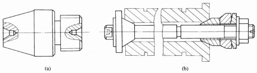
Figure 6-1-31 Cone bushing and cone sleeve mandrel: (a) Cone plug; (b) Cone bushing spindle
As the analysis demonstrates, the selection of positioning references in Table 6-1-10 for the spindle machining process follows this systematic approach. The process begins with rough machining of the outer diameter using the end face as a rough datum for milling center holes, establishing a positioning reference for rough turning. The rough-turned outer diameter simultaneously serves as a datum for drilling deep holes. Subsequently, to prepare positioning references for semi-finishing and finishing operations, front and rear conical holes are machined first to accommodate conical plugs, which utilize their two center holes as positioning references. Finally, the journal surface is ground before conical hole grinding to establish the support journal as the positioning reference. This comprehensive consideration of positioning references across all machining stages exemplifies the principle of **mutual datuming**.
Division of Machining Phases.
As shown in Table 6-1-10, it is crucial to divide the machining process into distinct stages based on the principle of separating roughing and finishing operations. This is because the spindle blank has significant and uneven machining allowances. Removing large amounts of metal can cause internal stress redistribution and deformation. Therefore, spindle machining typically follows a **three-phase approach** centered on primary surface processing:
- **Roughing stage** (including rough turning of all external diameters and drilling center holes)
- **Semi-finishing stage** (including semi-finishing turning of external diameters and conical end holes, along with center hole finishing)
- **Finishing stage** (including rough and precision grinding of external diameters or conical holes)
Secondary surfaces are appropriately integrated into these phases. The division of stages is generally based on **heat treatment boundaries**, with the entire process divided into roughing and finishing phases. This principle guides process planning to ensure machining quality and reduce production costs. For standard precision spindles, precision grinding serves as the final step. Precision spindles also require an additional polishing stage.
Arrangement of heat treatment process.
In the whole process of spindle machining, enough heat treatment process should be arranged to ensure the mechanical properties and machining accuracy requirements of the spindle, and improve the machining properties of the workpiece.
- After the forging of the spindle blank, the first arrangement is **normalizing treatment**, in order to eliminate the internal stress of forging, refine the grain, and improve the cutting performance during machining.
- During rough machining, operations like rough turning and drilling remove most of the workpiece material from the spindle. The intense cutting forces and heat generated during this phase create significant internal stresses. **Quenching and tempering** treatment can effectively eliminate these stresses and should be scheduled immediately after rough machining.
- After semi-finishing, for critical surfaces with remaining finishing allowance (support journals, mating journals, and tapered holes), **quenching treatment** is applied to achieve the specified hardness requirements, ensuring wear resistance. Subsequent precision machining processes can eliminate deformation caused by quenching.
Machining Sequence Arrangement.
The machining sequence follows the principle of **"base surface first, roughing before finishing, primary before secondary"**. For spindle components, the standard procedure involves preparing the center hole first, then machining the outer diameter followed by the inner bore, with roughing and finishing operations conducted separately.
In the CA6140 horizontal lathe spindle machining process, heat treatment serves as the critical marker: **rough machining precedes quenching treatment, semi-finishing follows quenching, and finishing occurs after quenching.** By separating these stages, the final precision of critical surfaces is ensured, preventing stress-induced deformation during subsequent surface machining processes.
When arranging the order of spindle process, we should also pay attention to the following points:
- **Deep hole machining** should be scheduled after quenching and tempering. Since quenching and tempering causes significant deformation, any bending deformation in deep holes becomes difficult to correct. This not only hinders the passage of bar stock during subsequent machine operations but also leads to spindle imbalance during high-speed rotation. Additionally, deep hole machining should be scheduled after rough turning or semi-finishing of the outer diameter, ensuring a precise shaft neck serves as the positioning reference.
- When machining the outer cylindrical surface, the **large diameter outer cylinder should be machined first**, and then the small diameter outer cylinder should be machined, so as to avoid reducing the stiffness of the workpiece at the beginning.
- **Secondary surfaces** such as splines and keyways on the spindle should generally be machined after external cylindrical finishing or rough grinding, but **before precision grinding**. This prevents compromising machining quality due to intermittent cutting or damaging the precision surfaces after final grinding.
- The **thread surface machining** on the spindle should be arranged after the local quenching of the spindle, so as to avoid the deformation after quenching affecting the coaxiality of the thread surface and the supporting shaft neck.
- **Grinding of spindle taper hole** is the key process. To ensure coaxiality, the grinding process typically uses the **bearing journal as the positioning reference**. In batch production, specialized fixtures are predominantly employed for machining.
二. Wheel shaft machining process
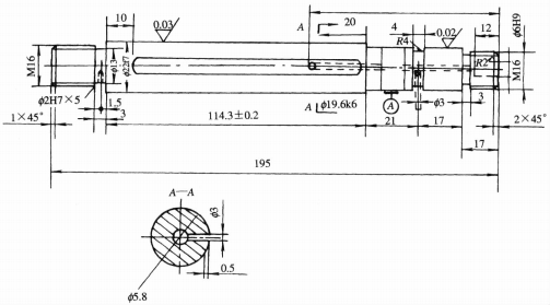
Figure 6-1-32: Pulley Shaft Working Drawing
Figure 6-1-32 shows the working drawing of a pulley shaft. The production type is **small-batch production**, and the material is **15 steel**. The pulley shaft's key technical requirements are twofold:
- The **carburizing layer depth** must be controlled within 1.2 to 1.5 mm.
- The outer diameter **φ22f7** requires carburizing and quenching, achieving a hardness of **58 to 63 HRC**.
It should be noted that only the φ22f7 section requires carburizing treatment, while the rest cannot undergo this process. For non-carburizing areas, excess material can be added to remove the carburizing layer after treatment or apply anti-carburizing coatings. The machining allowance should be slightly greater than the carburizing depth on one side. Therefore, the right end diameter is set at 425mm with a 2.5mm single-sided allowance for decarburizing, and both ends should have 3mm carburizing allowances. Since the outer diameter was already quenched before grinding, the center holes at both ends are prone to oxide formation and deformation during quenching, necessitating an additional grinding process.
Table 6-1-11 Lathe Spindle Machining Process (Pulley Shaft)
| operation number | Process content | Workplace |
|---|---|---|
| 1 | lathe | |
| 2 | Carburizing depth 1.5mm | heat treatment department |
| 3 | For carbon removal, machine both ends of the workpiece to achieve a total length of 195mm, ensuring equal dimensions at both ends. Drill a center hole on the right end, then machine the outer diameter to φ22f7 and φ19.7k6. Perform grinding with a depth of 0.3-0.4mm, thread the M16 to φ17mm, chamfer the thread, and countersunk to the specified dimensions. | Lath |
| 4 | Grind the flat surface to 104 × 0.5 mm dimensions, with the depth adjusted to exclude the grinding allowance. | arm brace |
| 5 | Drill holes with a depth of φ2H7 to φ1.8mm, φ5.8×82, and φ3 to specified dimensions, with a depth of φ6H9 to φ5.8mm. | drilling machine |
| 6 | Hardness 65 ~ 60HRC | heat treatment department |
| 7 | Thread size M16 at both ends | lathe |
| 8 | center lapping | center hole lapping machine |
| 9 | Bored holes φ2H7 × 5 and φ6H9 to size | bench |
| 10 | Grind the outer diameter to φ22f7 and φ19.7k6, then polish the shoulder surface to the specified dimensions. | Grinding machine |
三. Long slender shaft machining process
1. Machining characteristics of long slender shafts
- The long slender shaft has very **poor rigidity**. If the clamping is not proper during turning, it is easy to bend deformation and vibration under the action of cutting force and gravity, thus affecting the machining accuracy and surface roughness.
- The slender shaft has **poor thermal diffusion performance**, and under the action of cutting heat, considerable linear expansion will be produced. If the shaft is fixed at both ends, the workpiece will be bent due to elongation.
- Because the axis is long, the time of one pass is long, the tool wear is large, so as to affect the geometric shape accuracy of the part.
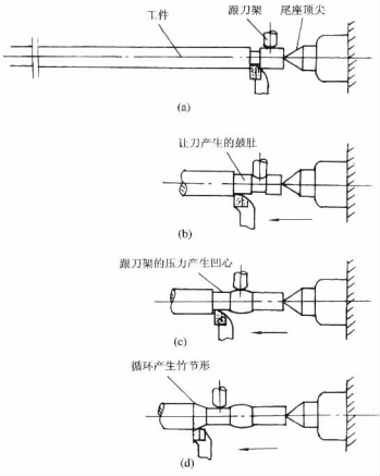
Figure 6-1-33: Formation process of the 'bamboo-joint' structure during machining of slender shafts
When machining slender shafts, the use of a tailstock may result in machining accuracy issues if the two support blocks exert improper pressure on the workpiece. Insufficient pressure or lack of contact will fail to enhance the part's rigidity, while excessive pressure may cause deformation.
- When the workpiece is pressed against the lathe tool, the increased cutting depth results in a smaller output diameter (see Figure 6-1-33(a)).
- As the follower continues to move, the support block rests on the outer surface of the smaller diameter, disengaging from the workpiece.
- The cutting force then pushes the workpiece outward, reducing the cutting depth and increasing the output diameter (Figure 6-1-33(b)).
- Subsequently, the follower returns to the larger diameter section, pressing the workpiece against the lathe tool again, thereby decreasing the output diameter (Figure 6-1-33(c)).
- This continuous and systematic variation process ultimately forms a **"bamboo-joint" shape** on slender workpieces (Figure 6-1-33(d)).
2. Reverse feed turning method
Figure 6-1-34 shows a schematic diagram of the **reverse feed turning method**, which is an advanced turning method for slender shafts. The characteristics are as follows:
- A ring of steel wire is wound around the left end of the slender shaft, and the three-claw self-centering chuck is used to clamp it, reducing the contact area, so that the workpiece can freely adjust its position in the chuck, avoiding the bending moment formed during clamping, and the deformation during the cutting process will not produce internal stress because the chuck is clamped.
- The tailstock top is changed to **elastic top**. When the workpiece is stretched due to **linear expansion** caused by cutting heat, the top can automatically retreat, so as to avoid bending deformation caused by thermal expansion.
- Three support blocks and tool holder are adopted to improve the rigidity of the workpiece and the stability of the axis, so as to avoid the formation of **"bamboo joint"**.
- Change the direction of cutting, so that the saddle moves from the spindle box to the tail seat, so that the workpiece is under **tension**, and it is not easy to produce elastic bending deformation.
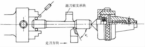
Figure 6-1-34 Reverse feed turning method
Conclusion
The core process for machining shafts is similar, but tool selection, support methods, and heat treatments must be adapted for each specific part to ensure its precision and strength.