What is Milling: From Basic Principles to Advanced Techniques?
Struggling to create precise metal parts? The wrong manufacturing process can lead to wasted time and money. Milling offers a versatile and accurate solution for your most demanding projects.
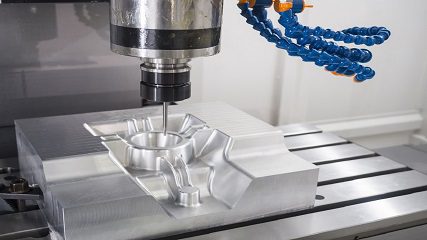
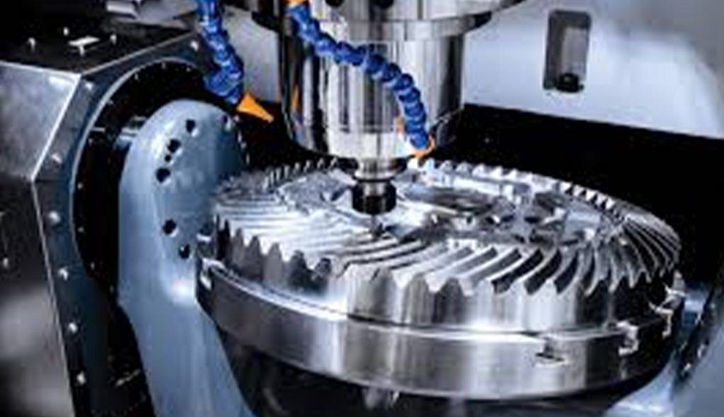
Milling is a fundamental machining process that uses a rotating multi-point cutting tool to remove material from a workpiece. It's incredibly versatile, capable of producing a wide range of features, from flat surfaces and pockets to complex 3D contours, making it essential for modern manufacturing.
Understanding milling is key to unlocking its full potential. At Worthy Hardware, we rely on this process every day to create custom parts for our clients. Let's look closer at how this process works and how it became the manufacturing powerhouse it is today. The more you know about the fundamentals, the better you can design parts that are efficient and cost-effective to produce.
What Are the Basic Concepts of Milling?
Milling is a subtractive manufacturing process. This means it creates a desired shape by removing material from a larger block, known as the workpiece or blank. The core of the process involves a cutting tool with multiple cutting points that rotates at high speed. The workpiece is fed into the rotating cutter, and each tooth on the cutter removes a small chip of material.
The main components in any milling operation are:
- Milling Machine: The machine that holds and rotates the cutting tool and also secures and moves the workpiece.
- Workpiece: The raw block of material (like aluminum, steel, or plastic) that will be shaped into the final part.
- Cutting Tool: Also called a mill or an end mill, this is the rotating tool with sharp teeth that performs the material removal.
- Workholding Device: A vise or fixture that holds the workpiece securely on the machine's table during the operation.
There are two primary types of milling operations, defined by how the cutting tool engages with the workpiece:
- Peripheral Milling: The cutting edge is on the periphery (the outside) of the tool. The axis of the cutter is parallel to the surface being machined. This method is often used for cutting deep slots, threads, and gear teeth.
- Face Milling: The cutting edge is on the face (the end) of the tool. The axis of the cutter is perpendicular to the surface being machined. This is used to create flat surfaces and to machine large areas down to the required height.
How Has Milling Evolved Throughout History?
The concept of milling has been around for centuries, but the machines we use today are vastly different from their early ancestors. The evolution of milling is a story of increasing precision, automation, and complexity.
1. The First Milling Machines (Early 1800s) The first true milling machine is often credited to inventor Eli Whitney in 1818. He needed a way to produce identical firearm parts more quickly than by hand filing. His machine allowed a workpiece to be moved along a table into a rotating cutter, marking a huge step forward in manufacturing repeatability. These early machines were simple and manually operated.
2. The Universal Milling Machine (1861) A major breakthrough came in 1861 when Joseph R. Brown of Brown & Sharpe designed the universal milling machine. This machine featured a table that could move in three axes (X, Y, and Z) and a swiveling table. This new freedom of movement made it possible to machine complex shapes like spirals, such as those needed for drill bits and gears. It set the standard for milling machine design for nearly a century.
3. The Introduction of Numerical Control (NC) (1950s) After World War II, the manufacturing industry needed a way to produce increasingly complex parts for the aerospace industry. The solution was Numerical Control (NC). Developed at MIT, NC machines used punched tape containing coded instructions to control the machine's movements. This removed the need for constant manual operation, allowing for the creation of complex curves and shapes with high accuracy. This was the birth of machine automation.
4. The CNC Revolution (1970s - Present) The development of computers led to the next major evolution: Computer Numerical Control (CNC). Instead of punched tape, CNC machines use a computer to read digital design files (like CAD models) and translate them into machine movements. This made the process more flexible, faster, and even more precise.
Key advancements in the CNC era include:
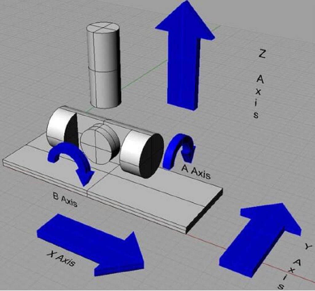
- Multi-Axis Machining: Early machines were limited to 3 axes (X, Y, Z). Modern machines, like the 5-axis CNC machines we use at Worthy Hardware, can move the tool and/or the workpiece along five different axes simultaneously. This allows us to machine extremely complex geometries in a single setup, improving accuracy and reducing production time.
- High-Speed Machining (HSM): Advances in spindle technology and cutting tools allow for much higher rotational speeds and feed rates. This removes material faster and can produce superior surface finishes.
- Advanced Software (CAD/CAM): Computer-Aided Design (CAD) and Computer-Aided Manufacturing (CAM) software have become incredibly powerful. We can design a part in a 3D environment and then use CAM software to automatically generate the optimal toolpaths for the CNC machine to follow. This simplifies programming and helps us avoid costly errors.
How Do Milling Machines Work?
To understand the process, let's break down the main components of a typical CNC milling machine, like the ones we operate daily at Worthy Hardware.
- Machine Frame: This is the main structure of the machine, usually made of heavy cast iron to provide rigidity and absorb vibrations. A stable frame is critical for achieving tight tolerances.
- Spindle: The spindle is the heart of the milling machine. It holds the cutting tool and rotates it at high speeds, which are measured in revolutions per minute (RPM). The power and speed range of the spindle determine what materials can be cut and how fast.
- Cutting Tool: This is the tool that does the actual cutting. Tools come in many shapes and sizes, like end mills, face mills, and drills, each designed for a specific type of cut. They are typically made from very hard materials like carbide or high-speed steel.
- Worktable: This is the surface where the workpiece is mounted. The table can move left and right (X-axis) and forward and backward (Y-axis).
- Knee and Saddle: On many vertical milling machines, the knee supports the saddle and the worktable. The knee moves up and down along the machine's column to control the cutting depth (Z-axis).
- Workholding: This is any device used to securely fasten the workpiece to the worktable. The most common is a vise, but custom fixtures are often built for complex parts or high-volume production runs. The part must not move at all during machining.
- CNC Controller: This is the brain of a CNC milling machine. It's a computer that reads a program (G-code) and translates the instructions into precise electrical signals that control the motors driving the axes and the spindle.
The actual milling process follows a clear sequence:
- Design and Programming: First, a 3D model of the part is created using Computer-Aided Design (CAD) software. We then use Computer-Aided Manufacturing (CAM) software to generate the toolpaths—the exact path the cutting tool will follow. This CAM software outputs a program called G-code, which is the language the CNC machine understands.
- Machine Setup: An operator prepares the machine. This involves securely clamping the raw material (the workpiece) in a vise on the worktable. Then, the correct cutting tool is loaded into the spindle. Finally, the operator sets the "work offset," which tells the machine the exact location of the workpiece's starting point (the X, Y, and Z zero).
- Executing the Program: The operator loads the G-code program into the CNC controller and starts the cycle. The machine takes over from here. The spindle spins up to the programmed speed, coolant starts flowing to lubricate the cut and cool the tool, and the worktable and spindle begin moving along the programmed paths.
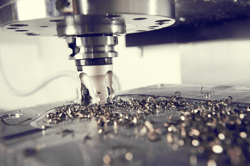
- Material Removal: The rotating cutting tool engages the workpiece, shearing off small chips of material with each rotation. The machine continues to follow the toolpaths, carving out pockets, drilling holes, and shaping contours until the final geometry is achieved.
- Inspection: Once the machining cycle is complete, the finished part is removed from the machine. We then perform a thorough inspection. At Worthy Hardware, every part is checked to ensure all dimensions are within the specified tolerances. We use precision measuring tools like calipers, micrometers, and even Coordinate Measuring Machines (CMMs) for parts with very tight requirements. This 100% inspection guarantee is a core part of our commitment to quality.
What Are the Different Stages in the Milling Process?
Stage 1: Design and CAD (Computer-Aided Design) Everything begins with a digital blueprint. Our process starts when a client sends us a design, typically as a 3D CAD model.
- What it is: A designer or engineer creates a precise 3D model of the part using software like SolidWorks, AutoCAD, or Fusion 360. This model contains all the geometric details, dimensions, and tolerances.
- Input Files: We typically work with standard file formats like STEP, IGES, or SLDPRT for 3D models, and DXF or DWG for 2D drawings.
- Our Role: Our engineers review the design for manufacturability (DFM). If we see a feature that could be difficult or expensive to machine, we proactively contact the client with suggestions for design improvements that can save time and reduce costs without compromising function.
Stage 2: Programming and CAM (Computer-Aided Manufacturing) Once the design is finalized, we translate it into instructions that the CNC machine can understand.
- What it is: A programmer uses CAM software to import the CAD model. They plan the entire machining strategy, including which tools to use, the order of operations, and the optimal cutting parameters.
- Key Parameters: This includes setting spindle speeds (how fast the tool rotates), feed rates (how fast the workpiece moves), depth of cut, and the path the tool will take (the "toolpath").
- Output: The CAM software generates a text file containing G-code. This is the specific command language that directs the CNC controller's every move.
Stage 3: Machine Setup This is the physical preparation phase where our skilled machinists get the machine ready for the job.
- Workpiece Mounting: The raw block of material (the workpiece) is securely fastened to the machine's worktable. This is usually done with a vise for simple shapes or a custom-built fixture for complex parts or large quantities. The workpiece must not move even slightly during machining.
- Tool Loading: The specific cutting tools determined in the CAM stage (e.g., end mills, face mills, drills) are loaded into the machine's tool holders and, if applicable, its automatic tool changer.
- Setting the Zero Point: The machinist carefully sets the "work offset." This tells the machine the exact X, Y, and Z coordinates of a reference point on the workpiece, establishing the starting point for all subsequent movements. This step is critical for accuracy.
Stage 4: Machining Execution This is where material removal happens.
- Running the Program: The machinist loads the G-code program into the CNC controller, performs a final check, and starts the machining cycle.
- Automated Cutting: The machine executes the program automatically. The spindle spins the cutting tool, coolant floods the cutting zone to lubricate and cool the tool and part, and the machine's axes move the tool and/or workpiece along the programmed toolpaths.
- Roughing and Finishing: The process often involves two main cutting phases. First, "roughing passes" remove large amounts of material quickly. Then, "finishing passes" are performed at slower speeds and with finer cuts to achieve the final dimensions and desired surface finish.
Stage 5: Post-Processing and Finishing A part is rarely complete right after it comes off the machine.
- Deburring: The machining process can leave small, sharp edges called burrs. By default, we deburr and break all sharp edges for safety and a clean finish.
- Surface Finishing: Depending on the client's requirements, the part may undergo additional finishing processes. At Worthy Hardware, we provide over 50 finishing options, including:
- Anodizing: Adds a durable, corrosion-resistant, and often colored layer to aluminum parts.
- Powder Coating: Applies a thick, protective layer of paint.
- Plating: Coats the part with another metal, such as zinc or nickel, for corrosion resistance or appearance.
- Polishing: Creates a smooth, reflective surface.
Stage 6: Quality Control and Inspection This is the final and most important stage in our process.
- What it is: Every single part we produce is thoroughly inspected to ensure it meets all the dimensions and tolerances specified in the original design.
- Tools We Use: Our quality assurance team uses a range of precision measuring instruments, including digital calipers, micrometers, height gauges, and for parts with very tight tolerances, advanced Coordinate Measuring Machines (CMMs).
- Our Guarantee: This commitment to 100% inspection is how we prevent issues like the ones our customer Mark has faced with other suppliers. It ensures that when you receive a shipment from Worthy Hardware, you can trust that every part is correct and ready to use.
What Types of Milling Operations Exist?
Primary Milling Categories
The two most fundamental categories are defined by the relationship between the cutting tool's axis and the workpiece surface.
- Peripheral Milling (or Plain Milling) In this operation, the axis of the rotating cutter is parallel to the surface being machined. The cutting teeth are located on the periphery of the tool. Think of it like a rolling pin moving across dough. Peripheral milling is used to machine flat surfaces, slots, and grooves.
- Slab Milling: Uses a wide cutter to machine a large, flat surface.
- Slotting: Uses a cutter with a specific width to create a slot or keyway.
- Straddle Milling: Employs two cutters on the same arbor to machine two parallel surfaces of a workpiece at the same time, ensuring they are perfectly parallel.
- Face Milling In face milling, the axis of the cutter is perpendicular to the surface of the workpiece. The cutting is performed by teeth on both the periphery and the face (end) of the tool. This is the most common method for creating flat surfaces on the top of a part. We use face mills with large diameters and replaceable carbide inserts to quickly remove material and achieve an excellent surface finish, making it a go-to operation for the first step in squaring a block of material.
Direction of Cut
Within these categories, there are two distinct ways the cutter can engage the material, which significantly impacts the process.
- Conventional Milling (Up Milling) The cutter rotates against the direction of the workpiece's movement (the feed). The chip starts very thin, thickens as the tooth cuts, and is then ejected. This method tends to lift the workpiece, so it requires very secure clamping. It was common on older, manual machines that had backlash in their lead screws.
- Climb Milling (Down Milling) The cutter rotates in the same direction as the workpiece feed. The tooth takes its thickest bite at the start of the cut and the chip thins out as it exits. This pulls the workpiece into the cutter, reducing tool wear and producing a better surface finish. On modern, rigid CNC machines with no backlash, climb milling is the preferred method for most applications due to its efficiency and quality. This is our standard approach at Worthy Hardware.
Specific Machining Operations
These operations are defined by the specific geometric feature they create. A single part often requires several of these operations.
- Pocketing: Machining a non-through cavity or "pocket" into a part. This can be any shape, such as a square, circle, or a more complex freeform shape.
- Slotting: Creating a narrow channel in a workpiece. This can be an open slot at the edge of a part or a closed slot within the part's body.
- Contouring: The milling cutter follows a path along the edge of a part to create the desired outline or "contour." This is used for shaping the outside profile of a component.
- Drilling: While technically a distinct process, it is almost always performed on a milling machine. A drill bit is used to create round holes.
- Tapping: Cutting internal threads into a pre-drilled hole. This is a common secondary operation performed on the milling machine.
- Thread Milling: An alternative to tapping, this process uses a rotating tool moving in a helical path to cut internal or external threads. It is more versatile than tapping because one tool can create threads of various diameters and pitches.
- Boring: Enlarging an existing hole to a precise diameter with a single-point cutting tool. Boring is more accurate than drilling for achieving tight hole tolerances.
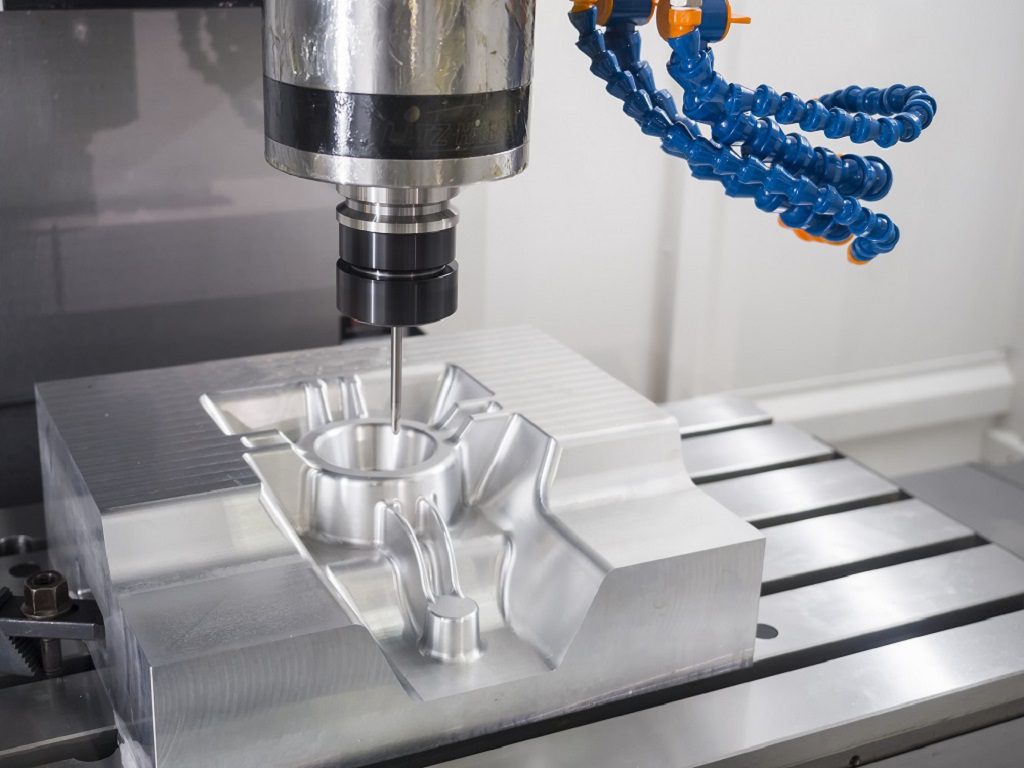
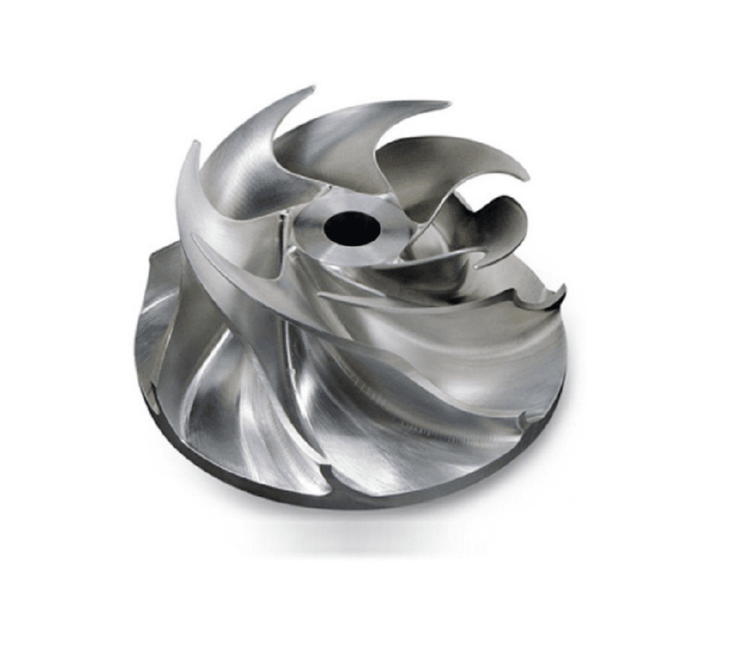
- 3D Surfacing: Used for creating complex, non-flat surfaces like those found on molds, turbine blades, or ergonomic consumer products. This often involves a ball-nosed end mill that follows a dense series of paths to replicate the 3D model's surface. This is where the capabilities of 5-axis CNC machining truly shine, allowing us to create intricate geometries in a single setup.
What Equipment Is Used in Milling?
Milling relies on a system of equipment. The core is the milling machine itself, which can be a 3, 4, or 5-axis CNC model. This is supported by workholding devices like vises, various cutting tools like end mills, and precision measuring instruments such as calipers and CMMs.
The Milling Machine: The Heart of the Operation
This is the primary piece of equipment. While manual mills still exist, the industry standard for precision and efficiency is the CNC (Computer Numerical Control) milling machine. They come in several configurations.
- Vertical Milling Machines: This is the most common type. The spindle axis is oriented vertically, and the cutting tool points straight down.
- 3-Axis: The tool moves up and down (Z-axis), while the table moves left-right (X-axis) and forward-backward (Y-axis). This is the workhorse for most flat parts, pockets, and profiles.
- 4-Axis: Adds a rotary axis (A-axis) to the worktable. This allows the workpiece to be rotated, enabling machining on multiple sides of a part without a new setup.
- 5-Axis: Adds a second rotary axis (B-axis or C-axis), allowing the tool or the part to tilt and rotate simultaneously. At Worthy Hardware, our 5-axis machines are crucial for manufacturing parts with complex, organic contours, such as those for aerospace or medical applications, in a single, highly accurate setup.
- Horizontal Milling Machines: In this configuration, the spindle axis is horizontal. These machines are often more rigid and are excellent for heavy cuts, slotting, and machining multiple parts at once on a tombstone fixture.
Workholding Equipment: The Foundation of Accuracy
Workholding refers to any device used to securely fasten the workpiece to the machine's table. This is critically important; if the part moves even a fraction of a millimeter during machining, it will be inaccurate and likely scrapped.
- Vises: The most common workholding device. Precision machine vises are used to clamp square or rectangular blocks of material.
- Clamps: A system of strap clamps, bolts, and blocks used to hold down irregularly shaped parts or parts that are too large for a vise.
- Custom Fixtures: For high-volume production or very complex parts, we design and build custom fixtures. These are plates or blocks engineered to hold a specific part in a precise location, repeatedly. This guarantees consistency across thousands of parts and speeds up setup time.
Cutting Tools: The Sculptor's Chisel
These are the tools that do the actual material removal. They are made from extremely hard materials like high-speed steel (HSS) or, more commonly, cemented carbide.
- End Mills: The most versatile milling tools, used for peripheral milling, pocketing, and contouring. They come in many varieties:
- Flat End Mills: For creating flat surfaces and walls.
- Ball End Mills: Have a rounded tip for 3D surfacing and creating fillets.
- Bull-Nose End Mills: Have a flat bottom with rounded corners, ideal for both roughing and finishing.
- Face Mills: Larger diameter cutters with multiple carbide inserts, used to quickly machine large, flat surfaces.
- Drills and Taps: Standard drills are used to create holes, and taps are used to cut internal threads into those holes.
- Tool Holders: These devices securely connect the cutting tool to the machine's spindle. The quality of the tool holder is critical for minimizing runout (wobble) and achieving precision.
Measurement and Inspection Equipment: Ensuring Quality
Machining to a specification is useless without the ability to verify it. This is why inspection equipment is as important as the milling machine itself.
- Hand Tools: Calipers, micrometers, and height gauges are used by every machinist for quick, on-the-spot measurements during setup and production.
- Gauges: Pin gauges are used to check hole diameters, and thread gauges are used to verify that tapped holes are correct.
- Coordinate Measuring Machine (CMM): This is the ultimate inspection tool. A CMM uses a highly sensitive probe to touch the part at multiple points, creating a 3D map of its geometry. At Worthy Hardware, our CMMs verify dimensions down to the tightest tolerances, including sub +/- 0.001" (+/- 0.025 mm). Our 100% inspection process relies on this equipment to guarantee that every part shipped meets the client's drawing perfectly.
Which Parameters Are Critical for Successful Milling?
The most critical parameters are spindle speed, feed rate, depth of cut, and width of cut. These four factors are interdependent and must be balanced to optimize material removal rate, achieve the desired surface finish, and maximize the cutting tool's lifespan for efficient,
1. Spindle Speed
- What it is: Spindle speed is the rotational speed of the cutting tool, measured in revolutions per minute (RPM). It dictates how fast the cutting edges of the tool move across the material's surface.
- Why it's important: The correct spindle speed is crucial for achieving a clean cut and managing heat.
- Too slow: Can cause the tool to "push" or "plow" through the material instead of shearing it, resulting in a poor surface finish and putting excessive force on the tool and machine.
- Too fast: Can generate excessive heat, leading to premature tool wear, tool failure, or even melting and deforming the material, especially in plastics.
- How it's determined: The ideal spindle speed is calculated based on the material being cut and the diameter of the cutting tool. Harder materials like stainless steel require slower speeds, while softer materials like aluminum can be machined at very high speeds. Our engineers use industry-standard formulas based on Surface Feet per Minute (SFM) or Meters per Minute (m/min) to determine the optimal starting RPM for each job.
2. Feed Rate
- What it is: Feed rate is the speed at which the workpiece is moved into the rotating cutting tool. It is typically measured in inches per minute (IPM) or millimeters per minute (mm/min).
- Why it's important: Feed rate directly controls the material removal rate (MRR) and the thickness of the chips being produced.
- Too slow: Leads to long cycle times and increased cost. It can also cause the tool to rub against the material instead of cutting, generating excessive heat and causing rapid tool wear.
- Too fast: Can put immense stress on the cutting tool, leading to chipping or breakage. It can also result in a rough surface finish and dimensional inaccuracies.
- How it's determined: Feed rate is directly related to spindle speed and a factor called "chip load," which is the thickness of the material removed by each cutting edge (tooth) of the tool. The goal is to create a perfectly formed chip, which efficiently carries heat away from the workpiece and the tool. Our CAM programmers carefully calculate the feed rate to balance speed with quality.
3. Depth of Cut (Axial Depth of Cut, or AP)
- What it is: This parameter refers to how deep the tool cuts into the material along its own axis during a single pass. It is the Z-axis engagement.
- Why it's important: Depth of cut is a primary driver of the material removal rate.
- Too shallow: Results in an inefficient process with many passes, increasing machining time and cost.
- Too deep: Can cause excessive tool deflection (the tool bends away from the workpiece), leading to dimensional errors and a tapered wall. It can also cause vibration (chatter), poor surface finish, and catastrophic tool failure.
- How it's determined: The optimal depth of cut depends on the rigidity of the machine, the tool holder, the cutting tool itself, and the material being cut. For "roughing" passes, we take deeper cuts to remove material quickly. For "finishing" passes, we use a very shallow depth of cut to ensure high accuracy and a smooth surface.
4. Width of Cut (Radial Depth of Cut, or AE)
- What it is: This is the width of the tool that is engaged in the material during a pass. It is the side-to-side engagement, measured perpendicular to the tool's axis.
- Why it's important: Width of cut determines the forces exerted on the side of the tool and how effectively chips are evacuated from the cutting zone.
- Too small: Can be inefficient, but is often used in high-speed machining (HSM) techniques with a very high feed rate.
- Too large: Engages too many teeth at once, which can increase cutting forces and vibration, especially when cutting into corners.
- How it's determined: This parameter is balanced with the depth of cut. A common strategy is to use a large depth of cut with a small width of cut, or vice-versa. At Worthy Hardware, our experienced programmers use advanced CAM strategies to vary the width of cut to maintain a constant tool engagement, which minimizes vibration and extends tool life.
Which Materials Are Compatible with Milling?
Almost any solid material can be milled. This includes a vast range of metals like aluminum, steel, and titanium; plastics such as ABS, PEEK, and Nylon; composites like carbon fiber; and even wood. The best choice depends on your application's specific mechanical, thermal, and chemical requirements.
Metals
Metals are the most frequently milled materials due to their strength and durability. The specific metal chosen dictates the final properties of the part.
- Aluminum (e.g., 6061, 7075): This is one of the most popular materials for CNC milling due to its excellent machinability and great strength-to-weight ratio. Aluminum 6061 is a versatile, cost-effective choice for many applications, while 7075 offers higher strength for more demanding uses. We use it extensively for automotive, aerospace, and consumer electronics parts.
- Steel (e.g., Stainless Steel, Alloy Steel, Tool Steel): Steel offers superior hardness, strength, and wear resistance.
- Stainless Steels (304, 316): Provide excellent corrosion resistance, making them ideal for medical instruments, food processing equipment, and marine components.
- Alloy Steels (4140): Are known for their toughness and are used for industrial gears, shafts, and fixtures.
- Tool Steels: Are extremely hard and used to make other tools, dies, and molds.
- Titanium: Known for its exceptional strength-to-weight ratio and biocompatibility, titanium is a premium material. It is challenging to machine but essential for high-performance aerospace components and medical implants.
- Brass and Copper: Chosen for their excellent electrical conductivity and corrosion resistance. They are commonly used for electrical connectors, plumbing fittings, and decorative parts.
- Other Metals: We also frequently machine materials like zinc, bronze, and magnesium alloys, each offering unique properties for specific applications.
Plastics
Plastics are a lightweight, corrosion-resistant, and often more cost-effective alternative to metals. Their machinability varies widely.
- ABS: A common, low-cost thermoplastic that is easy to machine. It is great for prototypes and general-purpose applications that don't require high strength.
- Delrin (Acetal): A strong, stiff plastic with low friction. Its natural lubricity makes it perfect for milling gears, bushings, and other moving parts.
- Nylon: Offers good mechanical strength and excellent wear resistance. It is often used for screws, nuts, and parts that experience sliding contact.
- Polycarbonate (PC): Valued for its incredible impact strength and optical clarity. It's used for machine guards, clear manifolds, and durable housings.
- PEEK: A high-performance thermoplastic with outstanding thermal, chemical, and mechanical properties. It is a metal replacement used in demanding aerospace, medical, and semiconductor applications.
- PTFE (Teflon): Known for its extremely low coefficient of friction and chemical inertness. It's used for seals, insulators, and non-stick surfaces.
Composites and Other Materials
Beyond traditional metals and plastics, milling can shape advanced materials for specialized applications.
- Carbon Fiber: This composite material offers an incredible strength-to-weight ratio, surpassing even aluminum and titanium. We mill it to create high-performance parts for racing, drones, and robotics. Machining it requires special tooling and dust extraction systems.
- Wood: Milling is also used for woodworking, from hardwoods and softwoods to engineered woods like MDF. Applications range from custom furniture and architectural models to jigs and fixtures.
What Are the Main Advantages and Applications of Milling?
The Advantages of CNC Milling
- High Precision and Tight Tolerances: This is the hallmark of CNC milling. Modern machines, like those at Worthy Hardware, can consistently produce parts with very high accuracy. We can hold standard tolerances of +/- 0.005" (0.127 mm) and, when required, can achieve precision tolerances below +/- 0.001" (0.025 mm). This level of accuracy is critical for parts that need to fit together perfectly.
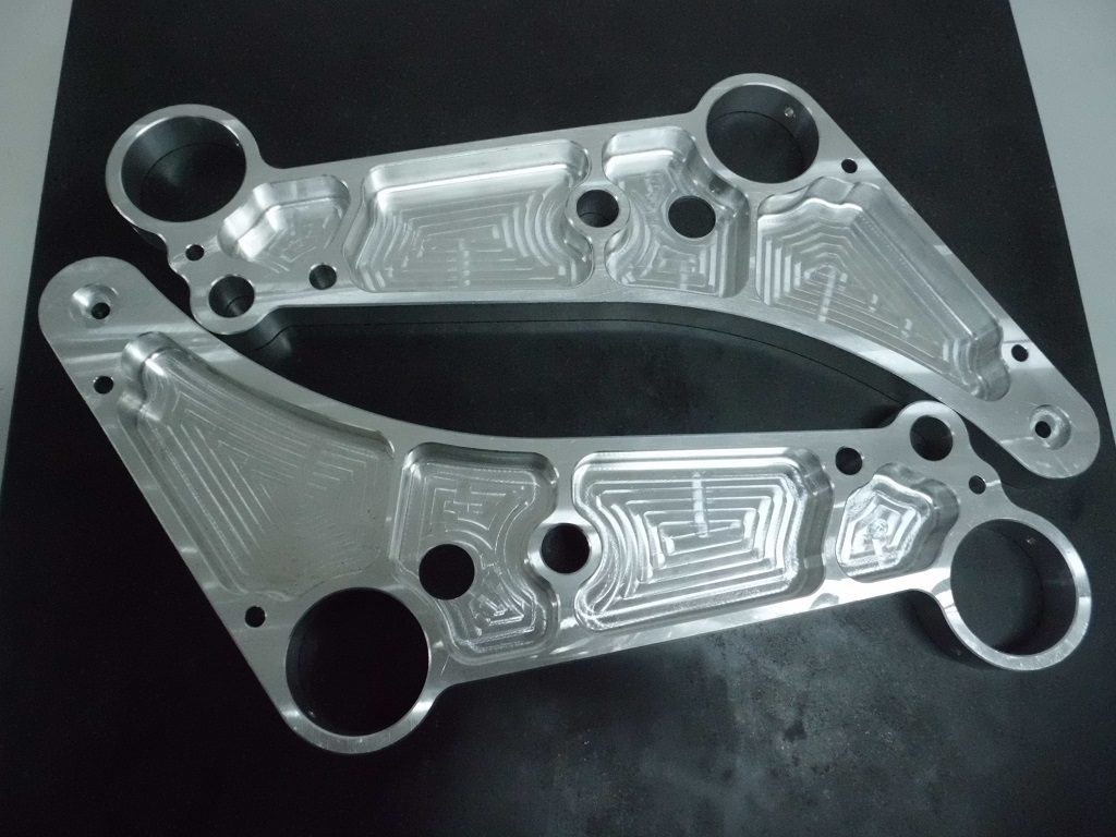
- Complex Geometries: Milling can create intricate shapes that are impossible with many other manufacturing methods. Features like pockets, slots, contoured surfaces, and angled holes are all standard operations. With 5-axis CNC milling, we can produce even more complex, multi-faceted parts in a single setup, ensuring accuracy and reducing costs.
- Material Versatility: As we've discussed, milling is compatible with an enormous range of materials. From soft plastics to hardened tool steels and superalloys, the process can be adapted to suit the material's properties. This gives designers immense freedom to choose a material based purely on the application's needs.
- Excellent Surface Finish: The milling process can produce very smooth and clean surface finishes. A standard as-machined finish is typically 125 Ra or better. Furthermore, parts can be polished, bead-blasted, or anodized to achieve an even better finish, making them suitable for high-end consumer products.
- Scalability: CNC milling is economically viable for both one-off prototypes and high-volume mass production. The process is the same whether making one part or ten thousand. For larger quantities, we can optimize the process with custom fixtures and automated tool changes to drive down the cost per part, offering services from prototyping to high-volume CNC machining.
Common Applications of CNC Milling
The combination of these advantages makes milling a cornerstone technology across numerous high-tech industries. When a client like Mark Chen from Canada needs high-quality OEM parts, they are often produced via milling.
- Aerospace and Defense: This sector demands the highest level of precision and reliability. Milled parts include engine components, structural brackets, landing gear components, and housings for sensitive electronics, often made from high-strength aluminum or titanium.
- Automotive: From engine blocks and transmission cases to suspension components and custom fixtures for assembly lines, milling is used throughout the automotive industry. It is essential for both high-performance racing parts and reliable components for everyday vehicles.
- Medical and Dental: Biocompatible materials like stainless steel, titanium, and PEEK are milled to create surgical instruments, orthopedic implants (like knee and hip replacements), and custom dental prosthetics. The precision of CNC milling is a matter of patient safety in this field.
- Electronics and Semiconductors: Milling is used to create heatsinks, enclosures for electronic devices, and precision components for semiconductor manufacturing equipment. The ability to machine aluminum and copper makes it ideal for thermal management applications.
- Consumer Products: The high-quality finish and precision of milling are perfect for premium consumer goods. Everything from the metal body of a smartphone or laptop to high-end kitchen appliances and sports equipment often contains CNC milled parts.
- Industrial Machinery and Robotics: The gears, shafts, brackets, and robotic arms that power modern automation are all made using milling. The process provides the strength and precision needed for machines to operate reliably for millions of cycles.
How Can Common Milling Problems Be Solved?
Problem: Poor Surface Finish
A rough, uneven surface is one of the most frequent quality complaints. It indicates that the cutting action is not clean.
- Common Causes:
- Incorrect spindle speed or feed rate.
- The cutting tool is worn, chipped, or has built-up material on its edge.
- Vibration (chatter) is occurring.
- The depth of cut for the final pass is too large.
- Solutions:
- Optimize Parameters: We recalculate the spindle speed and feed rate to match the specific tool and material combination. A higher spindle speed with a proper feed rate often "shears" the material more cleanly.
- Check the Tool: The tool is inspected for wear and replaced if necessary. A sharp, high-quality tool is essential for a good finish.
- Add a Finishing Pass: We program a final, separate pass that removes a very small amount of material (e.g., 0.010" or 0.25 mm). This light cut is performed with a sharp tool at optimized settings, specifically to create a smooth surface without the stress of heavy material removal.
Problem: Vibration (Chatter)
Chatter is a high-frequency vibration that you can often hear as a loud squeal or feel through the machine. It leaves a distinct, wavy pattern on the workpiece.
- Common Causes:
- Lack of rigidity in the setup.
- The cutting tool is sticking out too far from the tool holder.
- Incorrect cutting parameters that excite a harmonic frequency.
- Solutions:
- Increase Rigidity: This is the first step. We ensure the workpiece is clamped as securely as possible and as close to the machine table as practical. We also use the shortest possible cutting tool that can do the job, as a longer tool is more prone to deflection and vibration.
- Adjust Spindle Speed: Often, increasing or decreasing the RPM by just 10% can move the operation out of the harmonic window that causes chatter.
- Modify Cut Strategy: We change the depth of cut (AP) and width of cut (AE). A common solution is to take a deeper axial cut but a shallower radial cut.
Problem: Tool Breakage
A broken tool is a costly and time-consuming problem. It immediately stops production and almost always scraps the part being worked on.
- Common Causes:
- The feed rate or depth of cut is too aggressive for the tool and material.
- Poor chip evacuation—chips get packed in a pocket and are "recut" by the tool.
- The tool was already worn or chipped.
- Solutions:
- Reduce Cutting Forces: The most direct solution is to reduce the feed rate or the depth of cut. Our programmers calculate conservative but efficient parameters to ensure tool safety.
- Improve Chip Evacuation: We ensure a high-pressure stream of coolant is aimed directly at the cutting zone to forcefully flush chips away. For deep pockets where coolant can't reach, we use a high-pressure air blast.
- Use Ramping Entries: Instead of plunging a tool straight down into the material, we program it to enter on a gradual helical or ramped path. This significantly reduces the stress on the tool upon entry.
What Does Proper Milling Machine Maintenance Involve?
Daily Maintenance (Before and After Every Shift)
These are quick checks performed by the machine operator to ensure the machine is safe and ready for the day's work.
- Check Fluid Levels:
- Coolant: Verify the coolant level in the reservoir is sufficient. Low coolant can lead to poor surface finish and tool breakage. Check the concentration with a refractometer to ensure it provides proper lubrication and rust prevention.
- Lubrication: Check the way oil (for lubricating the machine's moving axes) and hydraulic fluid levels. Insufficient lubrication is the fastest way to cause permanent damage to the machine.
- Inspect and Clean:
- Wipe Down Surfaces: Clean the machine windows and wipe down critical surfaces.
- Chip Removal: Clear any large chip buildups from the work area, especially around the tool changer and way covers.
- Check Pressure Gauges: Quickly check the air pressure and hydraulic pressure gauges to ensure they are within the manufacturer's recommended range.
Weekly Maintenance
This involves a more thorough inspection and cleaning that goes beyond the daily checks.
- Thorough Cleaning: Remove all chips from the inside of the machine enclosure, including the chip conveyor and coolant tank. Old chips in the coolant tank can promote bacteria growth and clog filters.
- Filter Inspection:
- Coolant Filters: Clean or replace filters in the coolant system to ensure a clean, strong flow to the cutting tool.
- Air Filters: Check and clean the filters on the control cabinet's cooling fans. An overheating control system can cause electronic failures.
- Inspect Tool Holders and Chucks: Check the jaws of the chuck or the clamping mechanism of the tool holders for any damage or buildup that could affect accuracy or clamping force.
- Test Safety Features: Manually test safety interlocks and the emergency stop button to ensure they are functioning correctly.
Monthly Maintenance
These tasks focus on preserving the long-term accuracy and health of the machine.
- Grease Fittings: Apply grease to all specified points on the machine, such as the tool changer mechanism and other moving components, as outlined in the service manual.
- Check and Adjust Machine Level: Use a precision level to check if the machine is still perfectly level. A machine that is out of level can twist the frame, leading to inaccuracies in machined parts.
- Clean Radiators and Heat Exchangers: The heat exchangers for the spindle and control cabinet must be free of dust and oil to work effectively. Overheating is a primary cause of premature component failure.
Annual Professional Service
Beyond our internal schedule, we have our machines professionally serviced. This includes:
- Geometric Alignment Check: A service technician uses specialized laser equipment to check and verify the machine's geometric accuracy (squareness and straightness of all axes).
- Backlash and Drivetrain Inspection: The technician checks the ball screws and drive systems for wear and adjusts for any backlash (lost motion) to maintain positioning accuracy.
What Advanced Techniques Are Used in Modern Milling?
5-Axis Simultaneous Machining
This is perhaps the most significant advancement in modern milling. While a standard 3-axis machine moves the tool along the X, Y, and Z axes, a 5-axis machine adds two rotational axes (A and B, or B and C). This allows the cutting tool to approach the workpiece from a virtually infinite number of angles.
- How It Works: In "simultaneous" 5-axis milling, all five axes can move at the same time. This allows the machine to create incredibly complex, organic contours and curved surfaces in a single, continuous motion.
- Key Advantages:
- Complex Geometries: It is the only way to machine parts like turbine blades, propellers, and complex medical implants.
- Fewer Setups: A part that might require five or six separate setups on a 3-axis machine can often be completed in just one on a 5-axis machine. This dramatically reduces lead time and eliminates the risk of error that comes with repositioning the part.
- Better Surface Finish: The tool can be kept perfectly perpendicular to the part surface, resulting in a superior finish.
High-Speed Machining (HSM)
HSM is not just about running the machine faster. It is a comprehensive strategy that uses high spindle speeds combined with relatively light depths of cut and very fast feed rates.
- How It Works: HSM toolpaths, generated by advanced CAM software, are designed to be smooth and flowing, with no sharp corners. The machine is always moving, never stopping to change direction abruptly. This maintains a constant load on the cutting tool.
- Key Advantages:
- Faster Material Removal: Even with light cuts, the extremely high feed rates result in much faster cycle times compared to conventional roughing.
- Superior Surface Finish: The light, fast cuts produce a much smoother finish, often reducing or eliminating the need for secondary polishing.
- Longer Tool Life: By avoiding shock loads and managing heat effectively (most of the heat is carried away in the chip), HSM can significantly extend the life of our cutting tools.
Trochoidal Milling (Dynamic Milling)
This is a specific type of HSM toolpath designed for cutting deep pockets, slots, and channels, especially in tough materials like stainless steel or titanium.
- How It Works: Instead of a tool plunging and moving in a straight line, trochoidal milling uses a circular, spiraling motion. The tool is constantly moving, taking small radial cuts while maintaining a deep axial cut.
- Key Advantages:
- Efficient Deep Pocketing: It is the most effective way to evacuate chips from a deep pocket, preventing tool breakage from chip recutting.
- Reduced Tool Load: The technique maintains a consistent, low load on the tool, allowing us to machine hard materials much faster and more reliably than with traditional methods.
- Uses the Full Flute: It utilizes the entire cutting edge of the tool, distributing wear evenly and maximizing tool life. I remember a project with a deep pocket in 316 stainless steel that was causing constant tool breakage. Switching to a trochoidal toolpath solved the problem instantly and cut the cycle time in half.
Advanced CAD/CAM Software
None of these techniques would be possible without the powerful software that runs behind the scenes. Modern CAD (Computer-Aided Design) and CAM (Computer-Aided Manufacturing) systems are the brains of the operation.
- Role of CAM: Our engineers use CAM software to import a customer's 3D model and generate the complex toolpaths required for 5-axis and HSM. The software simulates the entire machining process, allowing us to detect any potential collisions or errors before the program is ever sent to the machine. This verification step is critical for protecting the part, the tool, and the machine itself.
Conclusion
Ultimately, modern milling relies on 5-axis machining, HSM, and trochoidal toolpaths to overcome traditional limits. Our team at Worthy Hardware uses these advanced methods every day. This allows us to deliver complex parts faster, with higher precision and better finishes, turning your most challenging concepts into tangible components.