What is Cutting Heat and Cutting Temperature in CNC Machining?

In the pursuit of perfect precision and cost-efficiency in CNC machining, have you ever considered the invisible force that can make or break your project's success? That force is cutting heat. Excessive temperature can warp materials, shorten tool life, and ultimately compromise the quality of your final parts. This guide breaks down the science behind cutting heat and temperature, revealing how they impact your machining outcomes and what factors you need to control for flawless results.
What is Cutting Heat?
Most of the energy consumed in the cutting process is converted into heat (called cutting heat), and only 1% ~ 2% of the work is stored in the workpiece material as strain energy to form a new surface and change the lattice.
How doese Cutting Heat Come From?
Cutting heat mainly comes from the following three aspects:
1)The heat Qb converted by the elastic and plastic deformation of the processed material per unit time;
2) The heat Qq generated by the friction between the tool's cutting edge and the chip base per unit time;
3) The heat Qh generated by the friction between the tool's back face and the workpiece surface per unit time.
Therefore, the heat generated per unit time during the cutting process is Q = Qb + Qq + Qh
If the work done in the feed motion is ignored, the heat generated per unit time is equal to the work done per unit time in the main motion:
Q = Fcvc
where Fc is the cutting force;
vc — Cutting speed.
What is Heat dissipation in cutting?
The cutting heat generated in the cutting zone is transferred through chips, workpiece, tool, and surrounding medium during the process. Therefore, in a thermal equilibrium state, the heat generated per unit time should equal the heat dissipated by chips, workpiece, tool, and medium, i.e.
Q = Qch + Qt + Qw + Qm
In this formula, Qch is the heat transferred to the chip per unit time;
Qt--heat transferred to the tool per unit time;
Qw--heat transferred to the workpiece per unit time;
Qm is the amount of heat transferred to the surrounding medium per unit time.
The percentage of heat dissipated by different components varies depending on factors such as workpiece material, tool material, cutting parameters, tool geometry, and machining methods. In dry cutting conditions, most cutting heat is typically carried away by chips, followed by the workpiece and tool, with minimal heat transferred to the surrounding medium. For example, during turning steel components, chips account for 50% to 86% of the cutting heat, the tool accounts for 10% to 40%, the workpiece accounts for 3% to 9%, and the surrounding medium (air) accounts for 1%. In drilling operations, chips carry away 28% of the cutting heat, the tool accounts for 14.5%, the workpiece accounts for 52.5%, and the surrounding medium accounts for 5%.
What is Cutting Temperature?
In the cutting process, the temperature of the workpiece, chip and tool at each point is usually different at a certain instant, and the temperature distribution, that is, the temperature field, changes with time. The cutting temperature generally refers to the average temperature of the contact area between the front tool and the chip.
The cutting temperature field is usually obtained by the measured method. Figure 1-3-12 shows the temperature distribution measured from the side of the tool by infrared photography when cutting low carbon steel, and Figure 1-3-13 shows the temperature distribution on the front and rear cutting surfaces in the main section plane when turning different workpiece materials.
As can be seen from Figure 2, the distribution of cutting temperature has the following characteristics:
Along the shear plane, temperatures remain nearly uniform across all points, while the temperature gradient perpendicular to this plane becomes highly pronounced. The highest temperatures on both the rake face and flank face are not located at the cutting edge but rather at a certain distance from it. The greater the brittleness of the workpiece material, the closer the peak temperature point is to the cutting edge. The temperature gradient perpendicular to the rake face also shows significant variation, with temperatures dropping markedly at 0.1–0.2 mm from the rake face. Materials with lower thermal conductivity (such as titanium alloys) exhibit higher temperatures on both the rake and flank faces, with the peak temperature point being closer to the cutting edge.
What are the main factors affecting cutting temperature?
(1)The influence of workpiece material:
The higher the strength and hardness of the workpiece material, the more cutting heat is generated, and thus the cutting temperature
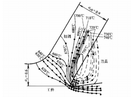
Figure 1-3-12 Temperature distribution in 2D cutting
Workpiece material: low-carbon easy-cutting steel; tool rake angle Yo = 30°, flank angle αo = 7°; cutting parameters
The thickness is hD = 0.6 mm, the cutting speed vc = 22.86 m/min, dry cutting, and preheating temperature
Up to 611℃
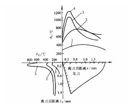
Figure 1-3-13 Temperature distribution of cutting different materials
Cutting speed vc = 30m/min, feed rate f = 0.2mm/r
1-45 steel-YT15 2-Gcr15-YT14
3—Titanium Alloy-YG8 4—BT2-YT15
The higher the degree, the greater the heat transfer rate; the lower the heat transfer coefficient of the workpiece material, the slower the heat transfer rate, and the higher the cutting temperature. Generally, the strength of alloy steel is greater than that of carbon steel, and the heat transfer coefficient is lower than that of carbon steel, so under the same conditions, the cutting temperature is much higher.
The plastic deformation and friction of cast iron and other brittle metal materials are small, and the heat generated is small, so the cutting temperature is generally lower than that of carbon steel.
(2)The influence of cutting parameters
The cutting speed has the greatest influence on cutting temperature, followed by feed rate.
Cutting depth has the least impact. For example, when turning 45 steel (annealed) with YT15 tool, doubling the cutting speed raises the temperature by 20% to 30%; doubling the feed rate increases the temperature by about 10%; while doubling the cutting depth only raises the temperature by 3%.
(1) Influence of Tool Geometric Parameters
The primary factors affecting cutting temperature are rake angle and principal rake angle. Cutting temperature decreases with increasing rake angle Y!, showing the most significant reduction when the rake angle rises from 10° to 18°. However, when the rake angle exceeds 25°, the temperature drop slows down due to reduced heat dissipation capacity of the tool tip.
The main deflection angle is reduced, the nominal width of the cutting layer is increased, and the nominal thickness is reduced. Because the heat dissipation volume of the tool head is increased, the cutting temperature decreases.
(2)The influence of tool wear
Cutting temperature increases gradually with tool wear. When the wear value of the back tool surface reaches a certain value, its influence on cutting temperature increases, and the higher the cutting speed, the more significant the influence.
(3)Impact of Cutting Fluids
During machining, cutting fluids not only reduce heat generation by minimizing friction but also dissipate heat through fluid flow, effectively lowering cutting temperatures. Key factors influencing cutting temperature include thermal conductivity, specific heat capacity, flow rate, application method, and fluid temperature. In terms of thermal conductivity, oil-based fluids perform worse than emulsion fluids, which in turn are inferior to water-based cutting fluids.
How to Measure cutting temperature?
At present, the natural thermocouple method and artificial thermocouple method are widely used and simple and reliable methods to measure cutting temperature.
(1)Natural Thermocouple Method
This method utilizes workpieces and tool materials with different chemical compositions to form the hot junction of a thermocouple, while the tool and workpiece lead-out terminals are maintained at room temperature to serve as the cold junction. By comparing the thermoelectric potential generated in the circuit with the calibration curve, the average cutting temperature at the tool-workpiece interface can be determined. Figure 1-3-14 shows a schematic diagram of the device for measuring cutting temperature using the natural thermocouple method on a lathe. Both the tool and workpiece should be insulated from the machine tool during operation.
(2)Artificial thermocouple method
As shown in Figure 1-3-15, a thermocouple composed of two pre-calibrated metal wires is used. The hot end is fixed on the point to be measured on the tool (or workpiece), and the cold end is connected in series with the millivoltmeter. The measured value can be compared with the calibration curve to obtain the temperature of the measured point.
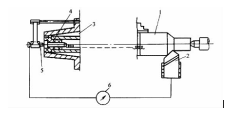
Figure 1-3-14 Measurement of cutting temperature by natural thermocouple method
1-Workpiece 2-lathe 3-lathe spindle tail
4-Copper pin 5-Copper tip 6-Millivoltmeter
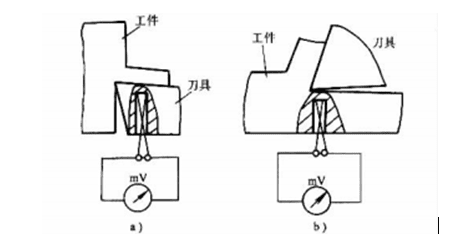
Figure 1-3-15 Measurement of tool and workpiece temperature by manual thermocouple method
a) Measurement of tool temperature b) Measurement of workpiece temperature
Conclusion
Ultimately, mastering cutting temperature is non-negotiable for achieving superior CNC machining results. By strategically managing workpiece material, cutting parameters, and tool geometry, we can mitigate thermal effects, extending tool life and ensuring your parts meet the highest standards of precision and quality with every single run.