What is CNC Turning
Struggling to create precise round parts with consistency? Manual methods are slow and often lead to errors. CNC turning provides a fast, automated, and highly accurate solution for perfect results.
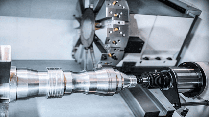
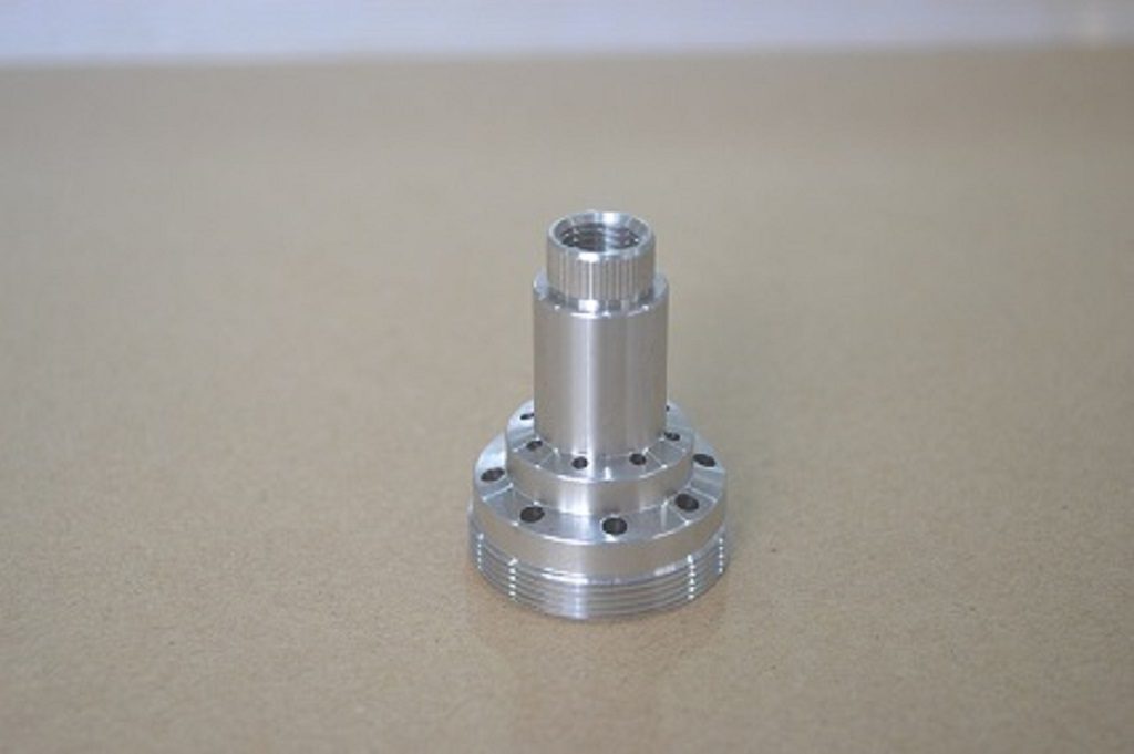
CNC turning is a manufacturing process where a block of material is rotated while a cutting tool removes material to create a cylindrical part. Think of it as a high-tech apple peeler. A computer controls the tool, ensuring every shaft, sleeve, or round component is dimensionally accurate.
The basic idea is quite simple. I often explain it to my clients as a high-tech version of peeling an apple. But to really understand its power for your projects, we need to look closer at the details. In this guide, I will explain everything from the basic definition to its historical development. Let’s dive deeper into the world of CNC turning.
What Are the Basic Concepts and Definition of CNC Turning?
At its core, CNC turning is a subtractive manufacturing process. This means we start with a solid block of material (the workpiece) and remove unwanted parts to reveal the final shape. The unique feature of turning is that the workpiece rotates at high speed while a stationary cutting tool does the cutting.
This process is performed on a machine called a lathe. In CNC turning, the lathe's movements are precisely controlled by a computer. We feed a digital design file into the computer, and it directs the cutting tool to create the part exactly as designed.
Here are the basic components involved in the process:
- The Lathe: This is the main machine. Its key components include:
- Spindle: The part that rotates the workpiece.
- Chuck: The fixture that securely holds the workpiece while it spins.
- Tool Turret: Holds various cutting tools. The computer can automatically switch between them to perform different operations like drilling, threading, or facing.
- The Workpiece: This is the raw material, typically a cylindrical bar. At Worthy, we work with over 100 materials, including metals like aluminum, steel, and titanium, and plastics like Delrin and PEEK.
- The Cutting Tool: This is a sharp implement, usually made of a very hard material, that is used to shape the workpiece. Different tool shapes are used to create different features on the part.
- The Computer (CNC Controller): This is the brain of the operation. It reads a set of instructions, called G-code, which tells the machine exactly how to move, how fast to spin the workpiece, and which tool to use. This automation is what guarantees precision and repeatability for every part we produce.
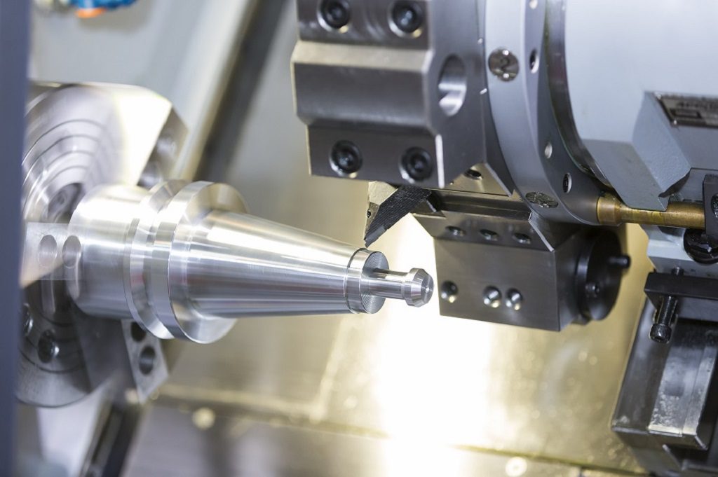
Because of this setup, CNC turning is ideal for creating any component that has a cylindrical or round profile. Common examples include shafts, pins, bushings, sleeves, and fasteners.
How Has CNC Turning Technology Evolved Throughout History?
The concept of turning is one of the oldest machining methods, but the technology we use today at Worthy is the result of a long evolution. Understanding this history helps appreciate the precision and efficiency we can now achieve.
- Early Manual Lathes: The earliest forms of lathes were powered by hand or foot. A skilled operator had to manually control the cutting tool with handwheels and levers. The quality and accuracy of the part depended entirely on the operator's skill. While effective, this process was slow and not suitable for mass production.
- The Rise of Numerical Control (NC): The first major step toward automation came in the 1940s and 1950s with Numerical Control (NC). Instead of manual control, machines were directed by a set of instructions stored on punched tape. This was a huge leap forward, allowing for the creation of more complex parts with better repeatability. However, creating and editing these tapes was difficult, and the system was not very flexible.
- The Computer Revolution (CNC): The real game-changer was the integration of computers in the 1970s and 1980s. This marked the birth of CNC (Computer Numerical Control) turning. Instead of punched tapes, instructions were stored digitally and could be easily created, edited, and loaded into the machine. This made programming much faster and more flexible.
- Modern CNC Turning: Today, CNC turning technology is highly advanced.
- Live Tooling: Modern CNC turning centers often include "live tooling," which means some tools in the turret can spin independently. This allows us to perform secondary operations like milling, drilling, and tapping on the part without moving it to another machine. This saves time and improves accuracy.
- Multi-Axis Machining: While basic turning happens on 2 axes, modern machines can have 3, 4, or even 5 axes of movement. This allows for the creation of incredibly complex geometries in a single setup.
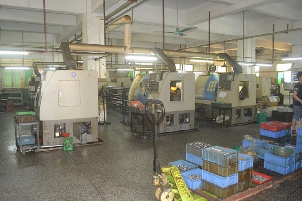
- Automation: At our facility, we integrate robotic arms to load raw material and unload finished parts. This allows for "lights-out" manufacturing, where the machines can run 24/7 with minimal human supervision, increasing efficiency and reducing costs for our customers.
What Are the Working Principles Behind CNC Turning Operations?
Here's how it works:
Rotation of the Workpiece:
The process begins with the workpiece, a block of material, being held firmly in a chuck and rotated at a high, constant speed. This speed, measured in Revolutions Per Minute (RPM), is a critical parameter determined by the material type, the cutting tool, and the desired surface finish.
Movement of the Cutting Tool:
While the workpiece spins, a non-rotating cutting tool is moved along two axes of motion by servo motors.
- Z-axis: This axis is parallel to the axis of rotation. The tool's movement along the Z-axis determines the length of the part's features.
- X-axis: This axis is perpendicular to the axis of rotation. The tool's movement along the X-axis controls the diameter of the part.
Computer Control:
The CNC controller is the brain of the operation. It reads a program called G-code, which contains a sequence of commands. These commands dictate every aspect of the process, including:
- Spindle Speed (S): The rotational speed of the workpiece.
- Feed Rate (F): The speed at which the cutting tool moves along the workpiece.
- Depth of Cut (DOC): The amount of material the tool removes in a single pass.
- Tool Path: The exact route the tool follows to create the part's geometry.
By controlling these variables with extreme precision, the CNC lathe shears material away from the spinning workpiece. This combination of rotation and linear tool movement allows us to create complex cylindrical shapes with tight tolerances, often as fine as +/- 0.001" or better.
What Are the Main Processes and Steps Involved in CNC Turning?
From a customer's initial design to the final shipped product, the CNC turning process follows a structured series of steps. At Worthy, we manage this entire workflow to ensure quality and efficiency for our clients.
Step 1: Design and Engineering Review
The process starts with the customer's design, usually in the form of a 2D technical drawing or a 3D CAD (Computer-Aided Design) file. Our engineers then conduct a Design for Manufacturability (DFM) review. We analyze the design to identify potential issues and suggest improvements that can reduce costs and lead times without compromising function.
Step 2: CAM Programming
Next, we use CAM (Computer-Aided Manufacturing) software to translate the 3D model into a set of instructions for the CNC machine. In this stage, our programmers define the entire machining strategy:
- Selection of the appropriate cutting tools and materials.
- Calculation of optimal parameters like spindle speed, feed rate, and depth of cut.
- Creation of the toolpath, which is the precise path the cutting tool will follow.
- Simulation of the entire process to verify the program and prevent any errors or collisions. The final output of this step is the G-code that will control the machine.
Step 3: Machine Setup
A skilled machinist then prepares the CNC lathe for production. This involves several critical tasks:
- Workholding: The raw material (a metal or plastic bar) is loaded and securely fastened into the machine's chuck.
- Tooling: The necessary cutting tools are installed in the tool turret.
- Calibration: The machinist sets the machine's reference points (work offsets). This tells the machine the exact position of the workpiece and the tools, ensuring the G-code is executed accurately relative to the material.
Step 4: Machining
With the setup complete, the G-code is loaded into the CNC controller, and the machining cycle begins. The machine automatically performs a sequence of operations as programmed, such as:
- Facing: Cutting a flat surface on the end of the workpiece.
- Roughing: Removing large amounts of material quickly.
- Finishing: Taking light passes to achieve the final dimensions and required surface finish.
- Grooving, Drilling, and Threading: Creating specific features on the part. The machinist closely supervises the production of the first part to confirm all dimensions and specifications are correct before proceeding with the full production run.
Step 5: Quality Inspection
Quality is central to our process. We perform 100% inspection on all products. Throughout and after the machining process, parts are measured using precision instruments like digital calipers, micrometers, and Coordinate Measuring Machines (CMM). This ensures that every part meets the specified tolerances and quality standards.
Step 6: Finishing and Shipping
After passing inspection, the parts may undergo secondary operations. This can include deburring to remove sharp edges, cleaning, or applying a surface finish such as anodizing, powder coating, or plating. Finally, the finished parts are carefully packaged and shipped to the customer according to our flexible delivery schedules.
What Are the Different Types of CNC Turning and When Should Each Be Used?
CNC turning is not a one-size-fits-all process. Different machines offer different capabilities, and choosing the right one is crucial for efficiency and cost-effectiveness. At Worthy, we operate a range of CNC lathes to match the specific needs of each project.
2-Axis CNC Turning
What it is: This is the most fundamental form of CNC turning. The cutting tool moves along two axes: the X-axis (in and out, controlling diameter) and the Z-axis (left and right, controlling length). The workpiece spins, but does not move along these axes.
When to use it: This is ideal for simple cylindrical parts with no complex features. Use it for producing shafts, pins, bushings, and simple fasteners where only external and internal diameters, faces, and tapers are needed. It is a very cost-effective method for high-volume production of simple components.
3-Axis CNC Turning
What it is: A 3-axis CNC lathe adds live tooling and a C-axis. Live tools are cutting tools like end mills or drills that can spin independently of the main spindle. The C-axis allows the main spindle to be accurately positioned and controlled as a rotational axis.
When to use it: This machine is used for parts that require milling-type features in addition to turning. For example, drilling a bolt pattern into the face of a flange or milling a flat section onto a round shaft. It eliminates the need for a second operation on a milling machine, saving setup time and improving accuracy.
4-Axis CNC Turning
What it is: This adds a Y-axis to the capabilities of a 3-axis machine. The Y-axis allows the tool turret to move up and down, perpendicular to the X-axis. This greatly expands the milling capabilities.
When to use it: A 4-axis lathe is necessary for creating more complex off-center features. It can accurately machine keyways, slots, and holes that are not on the centerline of the part. This is useful for complex automotive or industrial components.
5-Axis CNC Turning (Mill-Turn Centers)
What it is: These are highly advanced machines that combine a full-featured CNC turning center with 5-axis milling capabilities. They typically add a B-axis, which allows the milling head to pivot and rotate.
When to use it: This is the ultimate solution for "done-in-one" machining of the most complex parts. We use these machines for parts with intricate and organic shapes, like medical implants, aerospace turbine components, or complex valves. It allows for machining a part from all sides in a single setup, offering maximum precision and efficiency.
Swiss-Type Turning
What it is: This is a specialized type of CNC turning. The workpiece is fed through a guide bushing, and the tools cut the material right next to this bushing. The part is moved back and forth along the Z-axis by the headstock, rather than the tools moving.
When to use it: Swiss turning is the perfect choice for producing very long, slender, and small-diameter parts with extremely tight tolerances. The guide bushing provides support, preventing the material from bending or vibrating during cutting. It is the standard method for manufacturing medical screws, electronic connectors, and watch components.
Which Techniques and Methods Are Used in Modern CNC Turning?
On a CNC lathe, we can perform a wide variety of operations to create specific features on a workpiece. These techniques are the building blocks used to shape the final part.
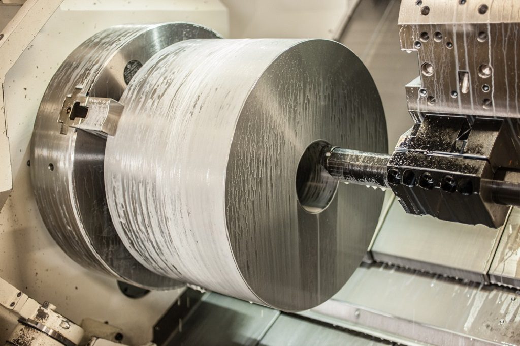
- Facing: This is usually the first operation performed. The tool cuts a flat, smooth surface on the end of the spinning workpiece. This creates a clean reference plane and sets the overall length of the part.
- Turning (Straight and Taper): This is the fundamental operation of reducing the workpiece's diameter. In straight turning, the tool moves parallel to the axis of rotation, creating a cylinder. In taper turning, the tool moves at an angle to the axis, creating a conical shape.
- Grooving: A grooving tool is plunged into the workpiece to cut a channel or "groove" of a specific depth and width. This is used for features like O-ring seats or reliefs for threading.
- Parting-Off: This is a specific type of grooving operation. A thin parting tool is plunged all the way to the center of the workpiece to cut the finished part from the main bar stock.
- Drilling: A drill bit is held stationary in the tool turret or tailstock and advanced into the center of the rotating workpiece to create a central hole.
- Boring: This technique is used to enlarge an existing hole. A boring bar with a cutting tip on its end is used to machine the internal diameter of a part to a precise size and achieve a good surface finish.
- Threading: This operation creates helical threads. The tool, shaped to the specific thread profile, moves along the Z-axis at a feed rate that is perfectly synchronized with the spindle's rotation. We can create both external threads (like on a bolt) and internal threads (like in a nut).
- Knurling: This is a forming process, not a cutting one. A knurling tool with a patterned wheel is pressed against the workpiece, creating a textured, grippable surface. This is commonly seen on handles, knobs, and thumb screws.
- Live Tooling Operations: On our more advanced 3, 4, and 5-axis lathes, we utilize live tooling to perform operations that would traditionally require a milling machine. These include:
- Cross-Drilling: Drilling holes on the side (diameter) of a part.
- Milling Flats: Creating a flat surface on a cylindrical part.
- Slotting: Milling a slot or keyway along the length of the part.
What Tools and Equipment Are Essential for CNC Turning Operations?
The CNC Lathe Machine:
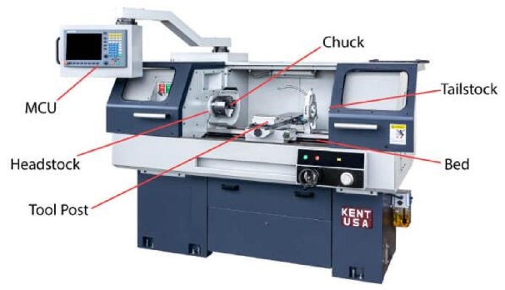
This is the core piece of equipment. Modern CNC lathes are complex machines consisting of several key parts:
- Headstock: This houses the main spindle and the motor that drives it.
- Spindle and Chuck: The spindle is the rotating shaft, and the chuck is the device mounted on it that securely grips the workpiece. Three-jaw chucks are common for round parts, while collets offer higher precision for smaller diameters.
- Tailstock: Positioned opposite the headstock, the tailstock provides support to the end of a long workpiece, preventing it from bending or vibrating during machining.
- Tool Turret: This is an indexable holder that houses a variety of cutting tools. The CNC program can automatically rotate the turret to bring the required tool into the cutting position.
- CNC Controller: This is the computer system that reads the G-code, interprets the instructions, and controls the movements of the machine's axes and spindle.
Cutting Tools:
The choice of cutting tool is critical and depends on the material being machined and the specific operation being performed. Common types include:
- Turning and Facing Tools: Used for reducing diameters and creating flat faces. These typically use replaceable carbide inserts.
- Boring Bars: Used for enlarging and finishing internal diameters.
- Drill Bits: Used to create holes in the center of the workpiece.
- Threading Tools: Specially shaped to cut external or internal threads.
- Grooving and Parting Tools: Thin tools used to cut grooves or to slice the finished part off the bar stock.
- Live Tooling: For multi-axis lathes, these include end mills, drills, and taps that can spin independently to perform milling operations on the workpiece.
Workholding Devices:
These are fixtures used to hold the workpiece securely. The choice depends on the part's size and geometry.
- Chucks: The most common workholding device.
- Collets: Provide excellent concentricity for small-diameter parts.
- Faceplates: Used for large, flat, or irregularly shaped parts that cannot be held in a chuck.
Measurement and Inspection Equipment:
To ensure that all parts meet the required specifications, we rely on a suite of precision measuring instruments. This is a cornerstone of our 100% inspection policy.
- Digital Calipers and Micrometers: For quick and accurate measurement of external and internal diameters, lengths, and feature locations.
- Coordinate Measuring Machine (CMM): A highly accurate device that uses a probe to measure the geometry of a part in three dimensions, providing a detailed report to verify complex features and tight tolerances.
- Optical Comparators: Project a magnified silhouette of a part onto a screen, allowing for easy inspection of profiles, threads, and other small features.
Which Parameters Most Significantly Affect CNC Turning Quality?
Cutting Speed: This is the relative speed between the workpiece surface and the cutting tool.
If the speed is too high, it generates excessive heat, leading to rapid tool wear and potential damage to the workpiece surface. If it's too slow, it can cause a "built-up edge" where material welds itself to the tool tip, resulting in a poor surface finish. The optimal speed is determined by the workpiece material, tool material, and the specific operation.
Feed Rate: This parameter defines how fast the cutting tool advances along its path.
feed rate will leave visible tool marks (scallops), creating a rough surface. A low feed rate produces a smoother finish but increases the cycle time. We use high feed rates for roughing passes (to remove material quickly) and low feed rates for finishing passes (to achieve the final surface quality).
Depth of Cut (DOC): This is the depth of material removed by the cutting tool in a single pass.A DOC that is too deep exerts excessive force on the tool and workpiece. This can cause the tool to break, the machine to vibrate (chatter), or the workpiece to deflect, leading to dimensional inaccuracies. We use a deep DOC for roughing and a very shallow DOC for the final finishing pass to ensure tight tolerances are met.
Tool Selection and Condition: The tool itself is a critical variable.
Using a tool with the wrong geometry (e.g., nose radius) can cause vibration or fail to create sharp corners. Most importantly, a worn or chipped tool cannot produce an accurate part. It will result in a poor surface finish and dimensional errors. We have strict protocols for monitoring tool life and replacing inserts to guarantee consistent quality.
Coolant Application: The use of cutting fluid (coolant) is crucial.
Coolant serves three primary functions: it cools the tool and workpiece, it lubricates the cutting action, and it flushes chips away from the cutting zone. Without proper cooling, high temperatures will destroy the tool and damage the part. Without chip evacuation, chips can get caught and mar the finished surface.
Machine Rigidity: The structural stiffness and condition of the CNC lathe itself.
Any looseness or vibration in the machine will be transferred directly to the workpiece, resulting in a poor, wavy surface finish known as chatter. It also makes holding tight tolerances impossible. This is why we invest in and meticulously maintain high-quality, rigid CNC machines.
Which Materials Are Best Suited for CNC Turning Operations?
1. Metals
Metals are the most frequently used materials in CNC turning due to their strength, durability, and conductive properties.
- Aluminum Alloys (e.g., 6061-T6, 7075-T6):
- Properties: Excellent machinability, high strength-to-weight ratio, and natural corrosion resistance.
- Suitability for Turning: Aluminum is ideal for turning. It allows for high cutting speeds and feed rates, which reduces cycle times. It forms predictable chips and can be machined to an excellent surface finish.
- Common Applications: Aerospace components, automotive parts, consumer electronics housings, and jigs and fixtures.
- Stainless Steel (e.g., 303, 304, 316):
- Properties: High strength, excellent corrosion and heat resistance.
- Suitability for Turning: Stainless steel is more challenging to machine than aluminum due to its toughness and tendency to work-harden. It requires lower cutting speeds, more robust tooling, and consistent coolant application. Grade 303 is specifically formulated with added sulfur for improved machinability.
- Common Applications: Medical instruments, food processing equipment, marine hardware, and chemical processing components.
- Carbon and Alloy Steel (e.g., 1018, 1045, 4140):
- Properties: High strength, durability, and cost-effectiveness.
- Suitability for Turning: Machinability varies by grade. Low-carbon steels like 1018 are soft and machine easily. Higher-carbon (1045) and alloy steels (4140) are harder and require slower speeds and more rigid setups to manage cutting forces.
- Common Applications: Shafts, gears, fasteners, axles, and general industrial machinery parts.
- Brass (e.g., C360 "Free-Machining Brass"):
- Properties: Exceptional machinability, good corrosion resistance, and excellent electrical conductivity.
- Suitability for Turning: C360 is often considered the benchmark for machinability. It allows for extremely high cutting speeds and produces small, easily managed chips, resulting in low tool wear and excellent surface finishes.
- Common Applications: Plumbing fittings, electrical connectors, consumer hardware, and musical instrument parts.
2. Plastics
Plastics are chosen for their light weight, chemical resistance, and insulating properties.
- Acetal (Delrin®):
- Properties: High stiffness, low friction, excellent dimensional stability, and good chemical resistance.
- Suitability for Turning: Delrin is one of the easiest plastics to machine. It cuts cleanly without melting, producing a smooth surface finish and holding tight tolerances well.
- Common Applications: Precision gears, bearings, bushings, and electrical insulators.
- Nylon:
- Properties: Good toughness and high wear resistance.
- Suitability for Turning: Nylon can be "gummy" to machine and requires very sharp tools to prevent melting. It is also hygroscopic (absorbs moisture), which can affect its dimensional stability after machining.
- Common Applications: Wear pads, rollers, seals, and high-impact components.
- PEEK (Polyether Ether Ketone):
- Properties: A high-performance polymer with outstanding mechanical strength and resistance to high temperatures, wear, and harsh chemicals.
- Suitability for Turning: PEEK machines well, similar to a soft metal, but its abrasive nature can cause accelerated tool wear.
- Common Applications: Components for aerospace, medical (implants), and semiconductor industries where performance under extreme conditions is critical.
What Are the Main Advantages and Limitations of CNC Turning?
CNC turning is a cornerstone of modern manufacturing, but like any process, it has a specific set of strengths and weaknesses. Understanding these helps our customers determine if it is the right choice for their parts.
Advantages of CNC Turning
- Exceptional Accuracy and Repeatability: The computer-controlled nature of CNC turning allows for the production of parts with extremely tight tolerances, often below +/- 0.001" (0.025 mm). Once a program is verified, the machine can produce hundreds or thousands of identical parts with minimal variation. This is fundamental to our 100% inspection guarantee.
- Excellent for Cylindrical Geometries: The process is inherently optimized for creating rotational parts. It can produce complex cylindrical, conical, and contoured surfaces with a speed and quality that other processes cannot match.
- Superior Surface Finish: By using fine-tuned finishing passes with a small depth of cut and slow feed rate, CNC turning can achieve very smooth surface finishes (as low as 16 Ra µin or better) directly off the machine, often eliminating the need for secondary grinding or polishing operations.
- High Production Efficiency: CNC lathes are designed for speed. Automated tool changes, high spindle speeds, and optimized toolpaths result in short cycle times. This makes the process highly cost-effective for everything from single prototypes to high-volume production runs.
- Material Versatility: As detailed in the previous section, CNC turning can be effectively applied to a wide range of materials, including almost all metals and many plastics, allowing for part production for diverse industries and applications.
Limitations of CNC Turning
- Limited to Rotational Symmetry: The primary limitation is that the process is best suited for parts that are largely cylindrical. While multi-axis turning centers can add some non-symmetrical features like flats and off-center holes, they cannot efficiently produce purely prismatic (square or block-shaped) parts. Such parts are better suited for CNC milling.
- Workholding Constraints: Long, thin parts can be difficult to machine due to the risk of deflection or vibration under cutting forces. While a tailstock or a specialized Swiss-type lathe can mitigate this, there are limits to the length-to-diameter ratio that can be machined accurately.
- Initial Setup Time and Cost: Creating the initial CNC program and setting up the machine (installing tools, calibrating offsets) requires skilled labor and time. While this cost is easily absorbed over a large production run, it can make single, very simple parts relatively expensive compared to manual machining.
- Internal Feature Limitations: While turning is excellent for creating external profiles, machining complex internal geometries can be challenging. The size and length of internal features are limited by the dimensions of the boring bars and other internal tools that can fit inside the workpiece without excessive vibration.
How Can Designs Be Optimized for CNC Turning Operations?

Specify Tolerances Wisely:
Principle: Only apply tight tolerances to critical features. The tighter the tolerance, the more time and care are required for machining and inspection, which increases cost.
Recommendation: For non-critical dimensions, use our standard tolerance of +/- 0.005" (+/- 0.127 mm). Reserve very tight tolerances, like +/- 0.001", only for surfaces that directly interface with other components. This is one of the most effective ways to reduce cost.
Avoid Sharp Internal Corners:
Principle: CNC turning tools have a rounded nose, which means they cannot create a perfectly sharp internal corner. They will always leave a small radius (fillet).
Recommendation: Design internal corners with a radius that is equal to or, ideally, larger than the tool's nose radius. A standard radius of 0.020" (0.5 mm) or larger is often a good starting point. Attempting to create a sharp corner requires a secondary, more expensive operation.
Maintain Uniform Wall Thickness:
Principle: Parts with very thin walls are prone to vibration and distortion during machining. This makes it difficult to hold tight tolerances and achieve a good surface finish.
Recommendation: Design walls to be as thick and uniform as possible. If a thin wall is unavoidable, understand that it may require special handling and slower machining, which can add to the cost.
Design Sensible Hole Depths:
Principle: Drilling very deep, small-diameter holes is challenging. Chips can become clogged, and the drill bit can wander off-center or break.
Recommendation: As a general rule, try to keep the depth of a drilled hole to less than 10 times its diameter. If deeper holes are required, they can be done, but they take more time and specialized tooling.
Use Standard Tool Sizes:
Principle: Our machine shops are equipped with a wide range of standard-sized drills, end mills, and grooving tools. Designing features that require custom-sized tools adds significant cost and lead time.
Recommendation: Design hole diameters, groove widths, and other features to match common, standard tool sizes whenever possible. For example, choose a 0.250" hole instead of a 0.245" hole if the function allows.
Consider Parting-Off Features:
Principle: The last step for many parts is parting them off from the bar stock. This operation works best on a simple, accessible feature.
Recommendation: Ensure there is a simple cylindrical section where a parting tool can easily access the part to cut it free. Avoid placing complex features right at the end of the part where it needs to be cut.
What Software Applications Support Modern CNC Turning Processes?
The journey from a digital idea to a physical part involves a chain of specialized software applications. Each piece of software plays a distinct role in ensuring the final component is machined accurately and efficiently. This software workflow is the backbone of our CNC turning operations.
| Software Type | Function | Role in the Process (How We Use It) | Common Examples |
| CAD (Computer-Aided Design) | Creates the digital blueprint of the part, including a 3D model and 2D technical drawings with all dimensions and specifications. | We receive customer CAD files, which our engineers use to view, measure, and analyze the design to prepare for manufacturing. | SolidWorks, Autodesk Inventor, Fusion 360, CATIA, AutoCAD |
| CAM (Computer-Aided Manufacturing) | Acts as the bridge between the CAD model and the CNC machine by planning the entire machining strategy. | We import the 3D model, select cutting tools, define toolpaths, and set cutting parameters. The final output is the G-code that directs the machine. | Mastercam, GibbsCAM, CAMWorks, integrated CAM in Fusion 360 |
| Simulation Software | Creates a virtual simulation of the machining process to verify the G-code program before running it on the physical machine. | As a critical risk-reduction step, we run simulations to verify toolpaths, check for collisions, and ensure the final part matches the design, preventing costly errors. | Often integrated as a feature within modern CAM software. |
| CNC Control Software | The operating system of the CNC machine itself, which reads the G-code file and executes the commands to control the machine's movements. | This software interprets the G-code and translates it into precise electrical signals that control the axes, spindle speed, tool changes, and coolant. | Fanuc, Siemens, Haas, Mazatrol (Specific to the machine controller brand) |
What Safety Hazards Should Be Considered in CNC Turning Operations?
Safety is the highest priority in any professional manufacturing environment. A CNC lathe is a powerful machine that combines high-speed rotation, powerful motors, and sharp cutting tools. At Worthy, we adhere to strict safety protocols to mitigate all potential hazards. The following are the primary safety concerns that must be managed during CNC turning operations.
- High-Speed Rotating Components:
- Hazard: The spindle, chuck, and workpiece rotate at thousands of revolutions per minute (RPM). Any contact with loose clothing, long hair, gloves, or rags can cause them to be instantly caught, leading to severe injury.
- Mitigation: Machine operators must never wear loose-fitting clothing or jewelry. Long hair must be tied back. Most importantly, the machine's safety doors must be closed and the interlocks engaged before a cycle is started. Operators must keep their hands and all tools away from the machine while it is in motion.
- Flying Chips and Debris:
- Hazard: The cutting process ejects small, sharp, and extremely hot metal chips at high velocity. These chips can easily cause severe eye injuries, cuts, or burns.
- Mitigation: The primary protection is the fully enclosed design of modern CNC machines. The safety glass doors contain the chips within the work area. All personnel in the vicinity of a running machine must wear approved safety glasses as a mandatory secondary precaution.
- Workpiece or Tool Ejection:
- Hazard: If a workpiece is not clamped securely in the chuck, the rotational forces can cause it to be thrown from the machine with lethal force. Similarly, a cutting tool that fails catastrophically can break into fragments and be ejected.
- Mitigation: We follow rigorous setup procedures. This includes ensuring the chuck jaws are correctly tightened, the workpiece is properly seated, and the clamping pressure is appropriate for the spindle speed and part mass. Tools are regularly inspected for wear, and cutting parameters are programmed to avoid excessive force.
- Automated Machine Movement:
- Hazard: The tool turret and machine axes are controlled by a computer program and can move rapidly and unexpectedly. An operator reaching into the machine at the wrong time could be crushed or struck.
- Mitigation: The door safety interlock is the most critical feature. It prevents the machine from running a program while the doors are open. Operators are trained to never bypass these safety features and to remain clear of the machine's travel paths.
- Cutting Fluid Exposure:
- Hazard: Coolants, or cutting fluids, can splash and create a mist. Prolonged skin contact can cause irritation or dermatitis, and inhaling the mist can lead to respiratory issues.
- Mitigation: The machine enclosure contains most of the splash and mist. Proper ventilation systems are used to maintain air quality in the workshop. Operators may be required to wear gloves or barrier cream to protect their skin.
- Electrical Hazards:
- Hazard: CNC machines use high-voltage three-phase power. The electrical control cabinets contain live components that present a severe risk of electric shock.
- Mitigation: Only trained and authorized maintenance technicians are permitted to open electrical panels. We strictly follow lock-out/tag-out (LOTO) procedures, which ensure the machine is completely de-energized before any service or repair work begins.
What Are Common Side Effects of CNC Turning and How Can They Be Resolved?
While CNC turning is a highly precise process, achieving perfect results requires careful control over many variables. Certain undesirable "side effects," or manufacturing defects, can occur. Our experienced engineers are experts at identifying and resolving these issues to ensure every part passes our 100% inspection standard.
- Poor Surface Finish
- Description: The surface of the part appears rough, scratched, or dull instead of smooth and bright.
- Causes: The feed rate is too high, the cutting speed is incorrect, the cutting tool is worn or chipped, or there is a lack of proper coolant.
- Resolution: We reduce the feed rate and use a shallow depth of cut for the final finishing pass. The cutting speed is optimized for the specific material. The tool insert is inspected and replaced if it shows any signs of wear. We also ensure a consistent flow of coolant is directed at the cutting edge.
- Chatter Marks
- Description: A distinct pattern of waves or spiral marks is visible on the machined surface, often accompanied by a loud, vibrating sound during cutting.
- Causes: This is caused by vibration. The source can be a lack of rigidity in the workpiece (if it is long and thin), the tool holder (if the tool is extended too far), or the machine itself.
- Resolution: To increase rigidity, we use a tailstock to support the end of long parts. We use the shortest, stoutest tool holder possible. We can also "tune" the machine by adjusting the spindle speed up or down by 10-15% to move away from the harmonic frequency causing the vibration.
- Dimensional Inaccuracy
- Description: The measured dimensions of the finished part do not fall within the tolerances specified on the drawing.
- Causes: Common causes include tool wear over a production run, heat causing the part to expand during machining, or incorrect tool offset values entered into the controller.
- Resolution: During production, we regularly measure parts and input tool wear compensation values to adjust for the shrinking size of the tool. Effective use of coolant helps maintain thermal stability. All tool offsets are carefully measured and double-checked during setup.
- Tapering
- Description: A part that should be a perfect cylinder is machined as a slight cone, with one end having a larger diameter than the other.
- Causes: This often occurs on long parts. It can be caused by the workpiece pushing away from the cutting tool due to cutting forces, or by a slight misalignment between the headstock and the tailstock.
- Resolution: We use a tailstock to provide rigid support against cutting forces. We also perform regular machine maintenance to ensure the headstock and tailstock are perfectly aligned along the machine's central axis. Reducing the depth of cut can also minimize the forces that cause deflection.
- Built-Up Edge (BUE)
- Description: A small piece of the workpiece material welds itself to the tip of the cutting tool. This BUE can then break off, damaging the tool and marring the part's surface.
- Causes: This is common when machining soft, ductile materials like aluminum or low-carbon steel at incorrect speeds.
- Resolution: The most effective solution is to increase the cutting speed. This raises the temperature in the shear zone and reduces the tendency for material to weld to the tool. Using coated tool inserts and applying a high-pressure flow of coolant also helps prevent BUE formation.
How Does CNC Turning Impact the Environment and Sustainability?
In modern manufacturing, we must consider our environmental impact. CNC turning, like any industrial process, presents both challenges and opportunities for sustainability. Understanding these factors is crucial for responsible production.
As a subtractive process, CNC turning inherently generates waste material in the form of chips or swarf. The machines also consume considerable electrical energy to power the spindle, axes, and control systems. Additionally, the cutting fluids used for cooling and lubrication require responsible management and disposal to prevent environmental harm.
However, CNC turning also offers significant sustainability advantages. The primary waste product, metal chips, is highly valuable and almost 100% recyclable. At Worthy, we meticulously collect and segregate materials like aluminum, steel, and brass, ensuring they re-enter the supply chain and reduce the demand for virgin resources.
Furthermore, precision is key to sustainability. By machining parts correctly the first time, we minimize scrap and rejected components, saving both material and the energy used in production. We optimize our processes with advanced CAM software to create efficient toolpaths. This reduces machining time, lowers energy consumption per part, and extends tool life. Responsible management of our coolants through filtration and recycling further minimizes our environmental footprint.
Is CNC Turning Cost-Effective Compared to Other Manufacturing Methods?
| Method Compared Against | When CNC Turning is More Cost-Effective | When the Alternative Method is More Cost-Effective |
| CNC Milling | For any part that is primarily cylindrical (e.g., shafts, pins, bushings, flanges). It is much faster and more efficient for producing rotational features. | For parts that are prismatic (square/rectangular) or have complex features on flat faces (e.g., pockets, slots, off-axis holes). |
| 3D Printing | For nearly all production volumes (1 to 1,000s), especially with metals. The per-part cost is lower, it's faster, and it yields superior mechanical properties and surface finishes. | For single, highly complex/organic prototypes, or parts with "unmachinable" internal geometries. Ideal for one-off plastic form-and-fit models. |
| Casting / Forging | For low to medium production volumes (from 1 to several thousand pieces). CNC turning has no tooling cost, avoiding the high initial investment for molds or dies. | For very high-volume production (tens of thousands to millions). The high tooling cost is absorbed, making the per-part price extremely low. |
How Should You Select a Professional CNC Turning Service Provider?
To select a professional CNC turning provider, evaluate them on five key criteria: documented quality systems (like ISO 9001), technical capabilities including equipment and tolerances, engineering support, proven experience in your industry, and transparent communication regarding lead times and logistics. A good partner offers more than just price.
- 1. Quality Systems and Inspection Processes
- What to Look For: The most fundamental factor is a commitment to quality. Ask for proof of a formal Quality Management System (QMS), such as an ISO 9001 certification. This shows they have documented and repeatable processes for maintaining quality.
- Key Questions:
- Do you provide inspection reports with every shipment?
- What inspection tools do you use (CMM, calipers, micrometers)?
- Can you guarantee 100% inspection on critical dimensions? (At Worthy, this is our standard procedure).
- 2. Technical Capabilities and Equipment
- What to Look For: The provider's equipment must match the requirements of your parts. This includes their ability to handle your required materials, part sizes, and, most importantly, tolerances.
- Key Questions:
- What are your machine's maximum part dimensions and tolerances? (Our capabilities include tolerances down to +/- 0.001" and lathe parts up to 62" in length).
- What is your range of available materials and surface finishes?
- Do you have multi-axis machines (like 5-axis) for more complex parts?
- 3. Engineering Support and Communication
- What to Look For: A great supplier acts as an extension of your team. They should have experienced engineers who can provide Design for Manufacturability (DFM) feedback. This helps you optimize your design to save cost and improve function. Responsiveness is also critical.
- Key Questions:
- Will your engineers review my design for potential cost savings? (Our team of 4 engineers specializes in this).
- What is your typical response time for quotes and technical questions?
- Who will be my single point of contact?
- 4. Proven Experience and Reputation
- What to Look For: Look for a track record of success, especially in industries similar to your own (e.g., aerospace, medical, automotive). This indicates they understand the specific standards and challenges of your field.
- Key Questions:
- Can you provide case studies or examples of similar parts you have manufactured?
- Which industries do you primarily serve?
- How long have you been in business and exporting to my country? (We have extensive experience shipping to North America, Europe, and Asia).
- 5. Lead Time, Logistics, and Pricing
- What to Look For: The provider must be able to meet your deadlines and handle international shipping smoothly. Their pricing should be transparent and competitive, but beware of quotes that seem too low—this can be a red flag for poor quality or hidden costs.
- Key Questions:
- What is your standard lead time, and can you accommodate urgent orders?
- Are you experienced with international shipping, customs, and logistics?
- Does your quote provide a clear breakdown of costs?
Conclusion
Choosing the right CNC turning partner is critical for success. At Worthy, we manage safety, quality, and sustainability to deliver cost-effective, precision parts. Contact us for a provider who offers expert engineering support and a 100% inspection guarantee on every order you place.