What Are the Conditioning Process in Heat Treating ?
Gas carburizing is a heat treatment process where a low-carbon steel part is heated in a furnace with a carbon-rich gas. This adds a thin, hard, wear-resistant layer of high-carbon steel to the surface while the core remains soft and ductile.
This process sounds complex, but it's a game-changer for creating durable parts. If you've ever wondered how manufacturers achieve that perfect balance of hardness and toughness in components like gears and bearings, you're in the right place. Let's explore how this essential heat treatment works, and if it's the right choice for your project. Keep reading to understand the details.

What Shoud We Do in the Preparation Stage?
(1) Device
1) Check whether the screw that fastens the furnace cover is broken and whether the sealing pad is intact.
2) Whether the lifting furnace cover mechanism, fan, cooling, lubrication, seepage agent supply system, etc. are normal.
3) Lift the carburizing tank regularly to check whether there are cracks and burnout, and whether the resistance wire is burned out or short circuit.
4) Remove carbon black, ash and oil from the carburizing tank, air inlet pipe and exhaust pipe.
5) Whether the electrical appliances and temperature measuring instruments are normal.
Carburizing agents
The raw material composition and characteristics of carburizing agents are shown in Table 3-7-36
3-7-36 Raw material composition and characteristics of carburizing agent
| Sealant types | Main ingredients and features | usage method |
kerosene | The main components are a mixture of paraffin, alkanes, and aromatic hydrocarbons. Kerosene for lamps should have a sulfur content of less than 0.1% to be usable. It has strong carburizing activity, but it is easy to form carbon black. If properly controlled, the large amount of carbon black can be avoided. | For direct injection into the furnace, the carbon concentration on the part surface is controlled by adjusting the droplet size. |
| Kerosene + Alcohol | Alcohol (C2HOH) is a colorless, transparent, and highly volatile substance that decomposes easily at high temperatures. Adding alcohol to kerosene reduces carbon black. | |
Methanol + Acetone | Methanol (CH3OH) and acetone (CH3COCH3) have simple molecular structures and are easily decomposed at high temperatures, but are not easy to produce tar and carbon black, but the price is relatively high |
(3) Tools
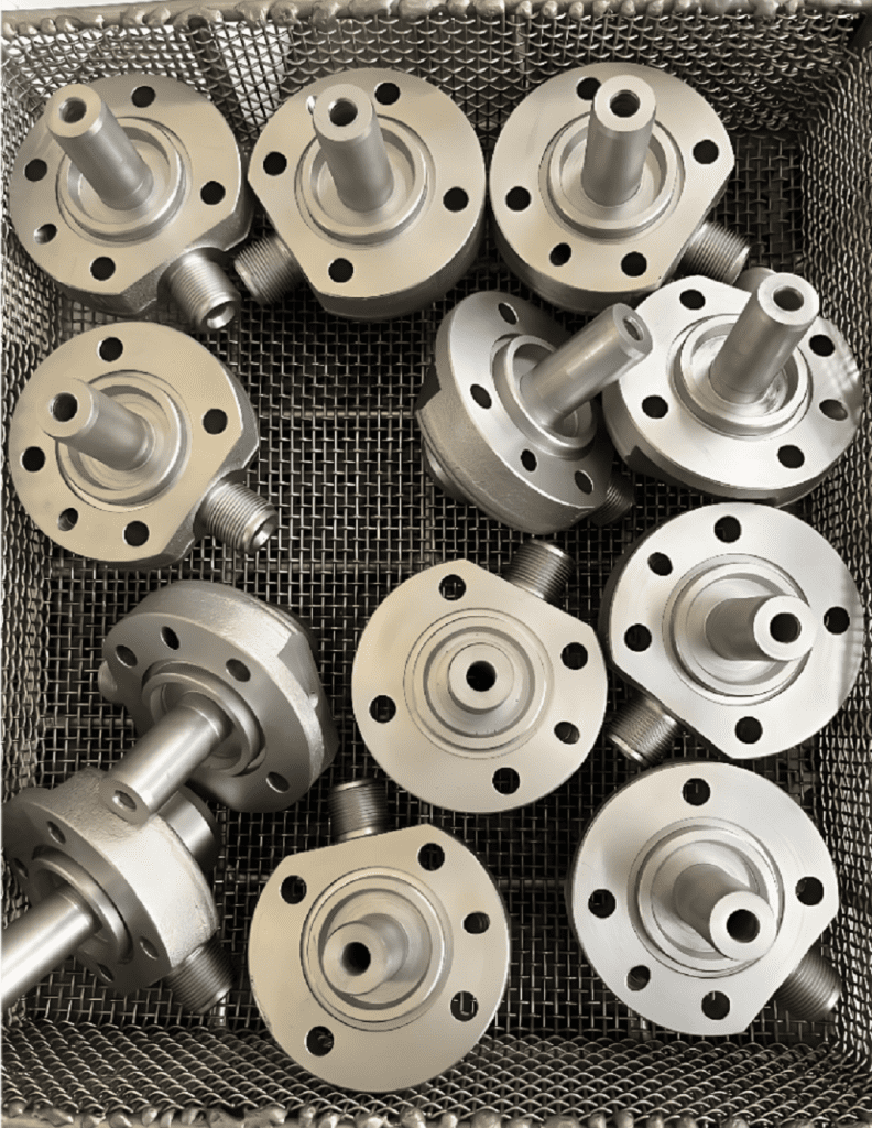
1) Prepare material baskets or other tools according to the shape, size, quantity and technical requirements of the carburized parts.
2) The lifting device should be able to lift or lift out the multi-layer material basket at one time.
(4) Requirements for parts
1) The surface of carburized parts should not have rust spots, oil stains and water marks.
2) The surface of the part shall not be damaged.
3) Protective measures should be taken for parts with local carburizing.
(5) Carburizing prevention method
1) The increased allowance method leaves a certain amount of machining allowance in advance in the parts that do not need carburizing, and the amount of allowance is more than twice the depth of the carburizing layer.
2) Copper plating method: Apply a 0.02-0.04mm copper layer to non-carburizing areas, ensuring the copper layer is dense and the original metal is not exposed.
3) Coating Method: Apply anti-seepage coating to areas that do not require carburizing. Commercial anti-seepage coatings are available for purchase. For self-preparation, refer to the following ratio (mass fraction):
Clay coating:
52% clinker clay (100-150 mesh, pre-fired at 920°C for 2 hours) 52%
32% sodium silicate with a modulus of 2.5 and density of 1.25 g/cm³ 32%
Tap water 16% 16%
Boron trioxide coating:
Boron trioxide (B2O3) 25% 25%
Borax 19.4% 19 .4%
Nickel trioxide (Ni2O3) 2.8% 2 . 8%
Copper oxide (CuO) 2.8% 2 . 8%
Polystyrene 10% 10%
40% toluene 40%
After degreasing, apply a 0.4 to 0.5 mm thick anti-seepage coating, which should dry at room temperature for 2 to 4 hours before loading into the furnace. This coating is suitable for carburizing treatment below 930°C.
(6) The sample shall be the same as the material of the part, and the same pre-heat treatment shall be applied. The surface shall be free of decarburized grain size 5 ~ 8, and the surface roughness Rα shall not be less than 6.3μm.
(7) Packing
1) The parts are classified according to the depth of carburizing layer specified by the process, and the same type of material with the same depth of carburizing layer can be loaded in one furnace.
2) There should be a certain gap between the parts in the material basket, and the layers should be separated by wire mesh or pad plates to ensure the permeation of the carburizing atmosphere and facilitate the uniform carburizing layer.
3) Thin plates or long parts should not be placed flat, but should be hung up to prevent deformation.
4) Check whether the anti-seepage part of the part is normal and whether the anti-seepage layer is falling off.
5) At least two samples should be placed in each material basket at representative positions in the furnace.
二 What Is The Process Specifications?
(1) Specifications and process curves for the small droplet carburizing process (see Figure 3-7-4)
(2) Large drop carburizing process specification
1) The carburizing process curve with large droplet volume is shown in Figure 3-7-5.
2) The types of carburizing agents and their drop quantities are shown in Table 3-7-37.
3) The depth of infiltration layer and insulation time are shown in Table 3-7-38.

Figure 3-7-4: Carburizing Process Curve with Droplet Measurement (RJJ-90 Well-Type Gas Carburizing Furnace)

Figure 3-7-5 Carburizing process curve with large droplet dosage
Table 3-7-37 Types of carburizing agents and their drop quantities
| stage | heating-up | keep warm | lower the temperature | ||||||||||||
| plant capacity /kw | 35 | 60 | 75 | 90 | 105 | 35 | 60 | 75 | 90 | 105 | 35 | 60 | 75 | 90 | 105 |
| carburant | Carburizing agent drops/min | ||||||||||||||
| kerosene | 30~ 50 | 40~ 60 | 60~ 80 | 70~ 90 | 80~ 100 | 100~ 120 | 110~ 130 | 130~ 160 | 160~ 180 | 160~ 200 | 60~ 80 | 100~ 140 | |||
| benzene | 60~ 100 | 80~ 130 | 130~ 150 | 180~ 200 | 10~ 50 | ||||||||||
Kerosene + Alcohol | Alcohol 140~ 160 | ethyl alcohol60 ~ 80kerosene100~ 120 | Alcohol 140~ 160 | ||||||||||||
Methanol + Acetone | Each 100~ 120 | carbinol60 ~ 80acetone120~ 140 | Each 100~ 120 | ||||||||||||
Table 3-7-38 Seepage depth versus thermal insulation duration
| steel products | structural carbon steel | alloy constructional steel |
| carburized depth /mm | soaking time /h | |
| 0 .40 ~ 0 .60 | 2~3 | 1 .5 ~ 2 .5 |
| 0 .60 ~ 0 . 80 | 3~4 | 2 .5 ~ 3 .5 |
| 0 . 80 ~ 1 .00 | 4 ~ 5 | 3 .5 ~ 4 .5 |
| 1 .00 ~ 1 .20 | 5~6 | 4 .5 ~ 5 .5 |
| 1 .20 ~ 1 .40 | 6~7 | 5 .5 ~ 6 .5 |
| 1 .40 ~ 1 .60 | 7~8 | 6 .5 ~ 7 .5 |
| 1 .60 ~ 1 . 80 | 8 ~ 10 | 7 .5 ~ 9 .5 |
三 What is the Operation method and precautions?
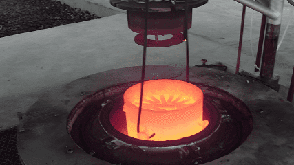
(1) Start heating the empty furnace to 850℃, then start dripping kerosene, ethanol or methanol exhaust. After reaching the temperature, cut off the power and open the furnace cover. Immediately load the material carrying parts into the furnace and put it in the right place. Close the furnace cover and tighten the screw.
(2) Connect the power supply of the temperature measuring instrument and the fan.
(3) According to the requirements of the process specification, adjust the pointer of the temperature instrument to the carburizing temperature.
(4) Drip the carburizing agent according to the process specification to ensure the dripping amount during the heating stage.
(5) When the furnace temperature rises to the carburizing temperature, the carburizing agent is dripped according to the requirements of the holding stage, and the holding time is recorded.
(6) After reaching the carburizing temperature, insert the sample into the furnace from the furnace cover sample hole. Generally, two samples are placed, and pay attention to sealing the sample hole to prevent air leakage.
(7) Check whether there is air leakage around the furnace cover and fan shaft to ensure that the furnace is under positive pressure.
(8) When the furnace works according to the normal specification for about 30 minutes, the sample is taken for furnace gas analysis, and the volume fraction of furnace gas composition is as follows:
| CO2 | 0 . 1% | CnHn | ≤0 . 2% |
| O2 | 0 . 2% ~ 0 . 8% | CO | 10% ~ 15% |
| H2 | 50% ~ 70% | CnH2n+ 2 | 10% ~ 15% |
The rest are N2
The exhaust gas should be ignited. Judging the working condition of the furnace according to the length and color of the flame, the normal flame is dark red, generally 80 ~ 250mm long.
(10 Check the stability of the number of carburizing agent drops regularly, and make necessary furnace records.
(11) 0.5 ~ 1.0h before the end of the heat preservation stage, a sample is drawn and tested to check the depth of the carburized layer by hardening fracture method or corrosion method, so as to determine the heat preservation time.
(12) The dripping amount of carburizing agent should be reduced in the uniform temperature stage.
(13) After the completion of the uniform temperature stage, the power should be cut off, the drip seepage agent valve should be closed, and then the furnace cover should be opened to get out.
(14) The carburizing basket is quickly lifted out of the furnace for air cooling (the parts with higher surface state requirements should be cooled in a cooling well with protective gas) or direct quenching.
(15) Take out the sample from the carburizing basket to check the depth of the carburizing layer, grain size and carbide.
(16) After stopping the furnace, the fan should be turned off only when the furnace temperature drops below 600℃.
四 What are The Causes and Solution of Common Defects
| Defect characteristics | Cause | resolvent |
Large or networked materials appear in the interlayer | The surface carbon concentration is too high, the seepage agent is too large, and the carbon increase is too strong | Select appropriate carburizing agents; or appropriately reduce the amount of carburizing agent during the heat preservation and diffusion stages |
The layer is too thick or too thin | The reason for excessive thickness is high temperature or long insulation time, large droplet size, and high carbon potential in the furnace; the reason for excessive thinness is low temperature or short insulation time, low carbon potential in the furnace and poor sealing | Adjust the carburizing temperature, time, and drop amount |
Uneven layer | The furnace has poor air flow and dead corners in some places; the surface of parts is not clean; the surface of parts is uneven in carbon deposition or uneven in roughness | Clean parts strictly; select appropriate fixtures; improve furnace loading method; clean carbon deposits in the furnace regularly |
| Surface oxidation and corrosion | The penetrant is impure, with excessive water and sulfur content; the carburizing tank leaks air; the surface of the parts is not clean | Take appropriate measures to address the causes |
Surface decarburization or carbon deficiency | Insufficient supply of carburizing agent; high temperature; slow cooling; prolonged exposure to air; poor sealing of carburizing tank; improper composition of carburizing agent | The composition of the infiltration agent and furnace gas must meet technical requirements. The infiltration agent must be added smoothly to the system, and the operation must be strictly controlled. |
Grain size is coarse or uneven | The original structure is not qualified; the carburizing temperature is too high | Select either fine-grained steel or pre-treat aluminum deoxidized steel (rapid cooling and normalizing at 1000℃-1200℃, followed by tempering at 700℃-750℃) |
The surface hardness is high after carburizing | The cooling speed is too high after baking | After carburizing, the workpiece is quenched to 650°C–700°C and then removed from the furnace, or subjected to high-temperature tempering. |
Conclusion
Gas carburizing is a vital heat treatment for creating steel parts with a hard, wear-resistant surface and a tough core, ensuring both durability and strength for critical applications