How to Machining of Inner Hole Surface of Sleeve Parts?
To machine the inner hole of a sleeve part effectively, you need a multi-step process based on your precision requirements. This usually starts with drilling to create the initial hole, followed by precision methods like boring for accuracy, reaming for a smooth finish, or honing for exceptionally tight tolerances.
Before we get into the specific techniques, it’s important to understand what exactly a "sleeve part" is and why its internal features are so critical.

What is Sleeve Parts?
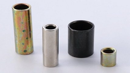
Hollow sleeve components are thin-walled parts used in rotating machinery, serving as essential support or guide elements in mechanical processing. These versatile components exhibit diverse structural configurations and dimensions depending on their functional requirements. Common applications include various bearing rings and bushings for rotating shafts, drill sleeves and guide sleeves in fixtures, cylinder liners for internal combustion engines, hydraulic cylinders in hydraulic systems, and valve sleeves for electro-hydraulic servo valves.
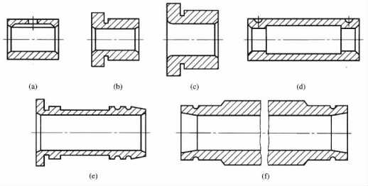
The general structural forms are illustrated in Figure 6-2-1. The structure and dimensions of sleeve parts vary according to their applications, but they generally have the following characteristics: the outer diameter d is generally smaller than the length L, usually L/d <5; the difference between the inner hole and the outer diameter is small, so the wall is thin and easy to deform; the coaxiality of the inner and outer rotating surfaces requires high; the structure is relatively simple.
Machining method of inner hole surface of sleeve parts
The primary machined surfaces of sleeve-type components include end faces, outer cylindrical surfaces, and inner cylindrical (hole) surfaces. End face and outer cylindrical machining are typically performed on lathes, which are relatively straightforward.
In contrast, inner cylindrical (hole) machining presents greater challenges. The tool diameter, length, and installation are constrained by the hole dimensions, making it more difficult to achieve the same dimensional accuracy for both inner holes and outer cylinders. This often requires multiple machining processes. Common hole machining methods include drilling, reaming, tapping, boring, broaching, grinding, as well as various finishing operations and special processing techniques.
1. Drill hole
Drilling is a machining process that creates holes in solid materials using drill bits. Typically performed with twist drills on drilling machines or lathes, this method faces challenges due to the drill bit’s relatively low strength and rigidity. These limitations result in difficulties with chip removal and coolant delivery, leading to relatively low precision and surface quality in the drilled holes. The standard precision typically ranges from **IT11 to IT13**, with surface roughness (Rα) values of 50 to 12.5 μm.
Boring tools often experience deviation during drilling, primarily due to three factors: asymmetric cutting edge grinding angles, improper positioning of the drill bit on the workpiece end face during operation, and the workpiece end face not being perpendicular to the machine spindle axis.
To prevent and minimize such deviations, the following measures are commonly adopted in drilling processes:
- Before drilling, process the end face of the workpiece to ensure it is perpendicular to the drill centerline.
- First, use a drill bit or center drill to pre-drill a pit on the end face to guide the drill bit.
- When grinding the drill bit, make the two main cutting edges symmetrical.
- When drilling small holes or deep holes, select a smaller feed rate to reduce the axial force of drilling and prevent the drill bit from bending and causing deviation.
- Drilling with workpiece rotation.
- Use a drill sleeve to guide the drill bit.
When drilling, the diameter of the drill bit is generally not more than 75mm. When drilling a larger hole (the diameter is more than 30mm), it is often used to drill twice, that is, first drill a smaller hole (0.5 ~ 0.7 times the diameter of the processed hole), and then use a large diameter drill bit to expand the hole to reduce the feed resistance.
2. Reaming
Reaming is a machining process that uses specialized tools to enlarge existing holes, improving both diameter and surface finish. The resulting holes typically achieve **IT10-IT13 precision** with surface roughness (Rα) ranging from **6.3 to 3.2 μm**. Reamers are commonly employed for this purpose. Compared to twist drills, reamers feature a flat cross-edge design, stable operation, compact chip clearance grooves, enhanced tool rigidity, and superior directional guidance, allowing for positional error correction.
Reaming serves as either a preparatory step before counterboring or as the final finishing operation. The reaming process and equipment are fundamentally similar to drilling, with a standard reaming allowance (D-d) of D/8. Reamers come in various diameters: conical reamers (10-32mm) and sleeve reamers (25-80mm) differ in size. Pre-counterboring reamers have negative diameter tolerance, while final reamers use positive tolerance. When machining steel with high-speed steel reamers, cutting speeds of 15-40m/min and feed rates of 0.4-2mm/r are recommended, achieving high productivity. However, reaming becomes impractical for holes exceeding 100mm in diameter due to excessive cutting torque, making boring the preferred method.
3. Broaching
Broaching is a precision machining method for unhardened holes. Due to its low cutting speed, minimal machining allowance, use of multiple-tooth reamers, specialized structure (combining cutting and correction sections), high rigidity, and superior accuracy, reamed holes achieve excellent quality with diameter tolerance typically ranging from **IT7 to IT10**. Reaming operations include manual and machine reaming. Manual broaching can achieve **IT6 dimensional accuracy** with surface roughness Rα of **0.4–0.2 μm**.
Machine reaming offers higher productivity and reduced labor intensity, making it suitable for mass production. Primarily used for machining holes of medium and small sizes (typically 3–150mm), reaming employs the existing hole as a guide. However, this method cannot correct positional errors, so positional accuracy must be ensured through pre-processing steps before reaming.
To guarantee machining quality during reaming, the following points should be noted: **Proper selection of reaming allowance and cutting parameters.** The reaming allowance varies depending on factors such as hole diameter, workpiece material, and precision requirements. For holes with diameters ranging from 5 to 80mm and precision grades of IT7 to IT10, the process typically involves rough reaming followed by finish reaming. Insufficient allowance often fails to completely remove machining marks from the previous process, while the tool teeth may slip along the hole wall under excessive pressure due to discontinuous cutting, resulting in reduced hole wall quality. Conversely, excessive allowance causes increased cutting forces and heat generation, leading to tool diameter expansion and vibration that may enlarge the hole. Refer to Table 6-2-1 for recommended machining allowances.
Table 6-2-1: Pre-drilling hole diameter and machining allowance (unit: mm)
| aperture 12 ~ 18 | > 18 ~ 30 | > 30 ~ 50 | > 50 ~ 75 | |
|---|---|---|---|---|
| Coarse Groove | 0.10 | 0.14 | 0.18 | 0.20 |
| finish ream | 0.05 | 0.06 | 0.07 | 0.10 |
| total allowance | 0.15 | 0.20 | 0.25 | 0.30 |
Proper selection of cutting speed can reduce chip accumulation and prevent surface quality deterioration. For boring cast iron, the recommended speed ranges from 8 to 10 m/min. When boring steel, the cutting speed should be lower than for cast iron: 4-10 m/min for rough boring and 1.5-5 m/min for finish boring. The feed rate during boring should not be too low, as insufficient feed causes excessively thin chips. This can lead to poor metal penetration, tool slippage, and even scraping damage, which compromises surface quality. Additionally, excessive feed may induce tool vibration and result in oversized holes.
Rational selection of pilot holes. The quality of pilot holes (previously machined holes) significantly impacts reaming accuracy. Poor precision in pilot holes makes achieving high reaming accuracy challenging. For instance, if the previous machining process causes shaft skewing, the small reaming allowance combined with the floating connection between the reamer and machine spindle makes correction during reaming difficult. For holes requiring high precision, preliminary operations like enlargement, boring, or rough reaming should be performed before precision reaming to minimize pilot hole errors, ensuring optimal reaming quality.
Proper Use of Reamers. As precision-cutting tools designed for fixed-size operations, reamers' performance directly impacts hole quality. The primary wear zone occurs on the back face where the cutting edge meets the shank, particularly at the junction between the cutting and shank sections. As wear progresses, the cutting edge's rounded radius increases, reducing cutting efficiency and causing excessive squeezing pressure that degrades hole quality. Field experience shows regular honing of this junction with oil stone during operation can significantly extend reamer durability. The extent of hole enlargement after reaming depends on specific machining conditions. For mass production, determine the reamer's outer diameter through field experience or trial runs before grinding. To prevent hole enlargement or "bell mouth" formation caused by misalignment between the reamer's axis, feed direction, and machine spindle axis, floating collets are typically used instead of rigid connections.
Proper selection of cutting fluid. Cutting fluid significantly impacts surface quality during reaming operations. Choosing the right fluid effectively reduces friction coefficients, improves heat dissipation, and removes fine chips. This not only enhances reaming quality and tool durability but also eliminates chip pockets, minimizes vibration, and reduces hole diameter expansion. High-concentration emulsion oil effectively reduces surface roughness, while sulfur-based oils significantly improve machining accuracy. When reaming general steel, the following considerations apply: Emulsified oil and vulcanized oil are commonly used. When milling cast iron, cutting fluid is generally not added. If the surface quality is further improved, kerosene with good wetting and low viscosity can be used as cutting fluid.
4. Boring
Boring is the most widely used hole-forming method, serving both roughing and finishing operations with broad applicability for creating holes of various sizes in different components. This process employs boring tools to refine pre-drilled, cast, or forged holes. Typically performed on boring machines, it can also be executed on lathes, milling machines, CNC machines, and machining centers. The machining accuracy ranges from **IT8 to IT10**, with surface roughness Rα values between **6.3 and 0.8 μm**.
Boring tools (boring bars and tools) are dimensionally constrained by the target hole diameter, often exhibiting poor rigidity that compromises precision and induces bending/twisting vibrations—particularly pronounced in small-diameter holes far from supports. While less productive than reaming or counterboring, boring remains cost-effective for small-batch production due to lower tool costs. It ensures precise hole centerline alignment and corrects axis deviations caused by raw material or previous machining processes. Given its extensive application scope, boring stands as one of the primary hole-forming methods. For exceptionally large-diameter holes and large components, it remains the only viable solution.
5. Grinding Holes
In the machining of holes in hardened components, grinding is the primary method. For internal holes with discontinuous circumferential surfaces (such as those with keyways or splines), stepped holes, and blind holes, grinding is typically employed as a finishing process. The grinding wheel size is constrained by the workpiece hole diameter, generally ranging from 0.5 to 0.9 times the hole diameter. The grinding head’s shaft diameter and length also depend on the hole’s diameter and depth, resulting in lower grinding speeds, reduced head rigidity, and compromised grinding quality and productivity. There are two grinding methods: **centerless internal cylindrical grinding** and **non-center internal cylindrical grinding**.
Centerless internal cylindrical grinding is performed on standard internal cylindrical grinders or universal grinders. Non-center internal cylindrical grinding is conducted on non-center grinders, where workpieces are typically thin-walled components unsuitable for chucking, requiring high coaxiality between inner and outer surfaces. This method is commonly used for grinding bearing ring-type components, characterized by high precision demands that require machine tools with advanced accuracy, automation, and productivity to support mass production.
Due to the harsher working conditions of internal cylindrical grinding compared to external cylindrical grinding, this method exhibits the following features:
- The diameter of the grinding wheel is limited by the diameter of the workpiece hole, about **0.5 ~ 0.9 times** the diameter of the hole. The smaller the diameter of the grinding wheel, the faster the wear, so it often needs to be repaired and replaced, increasing the auxiliary time.
- Using smaller diameter grinding wheels makes it challenging to achieve the required peripheral speed of 25-30 m/s during grinding. Consequently, the grinding speed is significantly lower than that for external cylindrical grinding, resulting in poorer surface quality of the holes and reduced production efficiency. In recent years, pneumatic grinding heads with 100,000 rpm have been developed to handle holes with diameters of 1-2 mm.
- The diameter of the grinding wheel shaft is limited by the aperture and length, and it is cantilevered, so the rigidity is poor, easy to bend and deform, so that the inner circle grinding wheel shaft is offset, thus affecting the machining accuracy and surface quality.
- The contact area between the grinding wheel and the hole is large, the pressure per unit area is small, the sand particles are not easy to fall off, the grinding wheel is hard, the workpiece is easy to burn, so it is better to choose a soft grinding wheel.
- Cutting fluid is not easy to enter the grinding area, chip removal is difficult, grinding chips are easy to accumulate in the gaps between the grinding particles, easy to block the grinding wheel, affecting the cutting performance of the grinding wheel.
- During grinding, the contact length between the grinding wheel and the hole frequently varies. When part of the grinding wheel extends beyond the hole, the contact length becomes shorter, resulting in reduced cutting force. This causes the grinding wheel spindle to produce less displacement compared to grinding the hole’s central section, leading to more metal removal and forming a **"bell mouth"** pattern. To minimize or eliminate this error, the grinding wheel’s protrusion beyond the hole should be controlled to no more than 1/2 to 1/3 of its width.
The internal cylindrical grinding accuracy can reach **IT7**, with surface roughness Rα ranging from **0.4 to 0.2 μm**.
6. Deep Hole Machining
(1) Technical characteristics of deep hole machining.
A hole is defined as deep when its depth-to-diameter ratio (L/D) exceeds 5. For holes with moderate L/D ratios, standard drills can be used on conventional drilling machines or lathes. However, deep holes with high L/D ratios require specialized tools, equipment, and advanced machining techniques. Deep hole processing is significantly more complex and challenging than conventional hole processing. The key technical features of deep hole machining include:
- The tool bar of deep hole machining is long and slender, and the strength and stiffness are relatively poor. It is easy to deviate and vibrate during machining, so it is very important to set the support and guide on the tool head.
- **Difficulty in chip removal.** If the chip blockage occurs, it may cause the tool to dull or even break, therefore requiring forced chip removal.
- The tool cooling and heat dissipation conditions are poor, the cutting fluid is not easy to inject into the cutting area, the tool temperature rises, the tool durability is reduced, so it is necessary to adopt effective cooling methods.
In deep hole machining, various process measures must be taken to solve the above three main aspects of the problem.
Deep hole drilling method.
In small-batch production, deep hole drilling is typically performed using extended twist drills on standard lathes or turret lathes. Sometimes workpieces require two installations to drill from both ends. During drilling, the drill bit must be repeatedly withdrawn to remove chips and cool the tool. This method is labor-intensive and inefficient in production. In mass production, deep hole drilling is widely adopted. Drill presses and deep hole drills are used for machining.
Deep hole machining typically employs two methods: rotating the workpiece or rotating both the workpiece and drill bit in opposite directions while advancing the drill bit axially. Neither method easily causes axis skewing in deep holes, with the latter being particularly advantageous, though requiring more complex equipment. For oversized workpieces where rotation is challenging, the workpiece can be fixed while rotating the drill bit for axial feed. However, when using this method, if the tool’s rotation centerline deviates from or intersects at an angle with the workpiece’s axis, the resulting hole axis will also exhibit deviation or skewing.
Cooling and Chip Removal Methods.
In deep hole machining, cooling (particularly of the cutting tool’s cutting edge) and chip removal are primary concerns. During the cutting process, most of the cutting heat is transferred to the chips. If chips can be discharged smoothly and efficiently, the cooling objective is achieved simultaneously with chip removal. Currently, there are three chip removal methods: **external chip removal, internal chip removal, and spray suction.** The most commonly used method is **internal chip removal**—where high-pressure cutting fluid is injected into the cutting zone through the gap between the drill rod and the workpiece hole wall, then carries the chips out through the inner bore of the drill rod. This method prevents chips from damaging the machined hole walls, ensuring better machining quality.
Special machining methods for sleeve parts
With the advancement of production needs and technological progress, a growing number of difficult-to-machine materials with high melting points, hardness, strength, brittleness, and toughness have emerged. Simultaneously, there has been an increasing demand for parts with complex structures and special process requirements. Traditional machining methods often struggle to meet these demands, leading to the rapid development of various special processing methods. These methods directly utilize electrical, chemical, acoustic, and optical energy for material processing.
They are primarily used for machining materials with poor machinability such as hard alloys, titanium alloys, heat-resistant steels, stainless steels, quenched steels, diamonds, gemstones, and ceramics. They also handle specialized applications like creating specific cross-sectional holes in molds, small holes and narrow slots in fuel injectors and spinnerets, as well as producing high-precision slender components, thin-walled parts, and low-stiffness elastic elements. Common special processing methods include **electrical discharge machining (EDM), electropolishing, ultrasonic machining, laser processing, electron beam machining, particle beam machining, and vibration cutting**.
Currently, many special processing techniques are evolving toward high precision and surface quality. This has led to the emergence of precision EDM and precision electropolishing, along with research to enhance laser machining accuracy (e.g., for small hole processing). Some methods like electron beam and particle beam machining are inherently ultra-precision techniques capable of removing and depositing individual molecules and atoms.
Therefore, special processing methods possess the following characteristics:
- Special processing mainly does not rely on tools and abrasives to cut, but uses electric energy, light energy, sound energy, heat energy and chemical energy to remove the excess metal and non-metallic materials on the parts, so there is no obvious cutting force between the workpiece and the tool, only a small force, and the mechanism is very different.
- Special processing not only removes excess metal and non-metallic materials from components, but also enables attachment processing, bonding processing, and injection processing. **Attachment processing** applies a material layer (such as coatings) to the workpiece’s surface. **Bonding processing** joins two workpieces or materials together through methods like laser welding or chemical bonding. **Injection processing** involves introducing specific metal ions into the surface layer of workpieces to modify their structure and achieve desired physical and mechanical properties.
- The hardness and strength of tools in special processing can be lower than that of workpieces, because it is not mainly cut by mechanical force, and some tools even have no loss, such as laser processing, electron beam processing, ion beam processing, etc.
Precision machining of holes
1. High-speed precision boring
High-speed precision boring, also known as **diamond boring**, is widely used for machining precision holes in structural components unsuitable for internal cylindrical grinding. Common applications include engine cylinder bore, connecting rod bore, piston pin bore, and transmission main shaft bore. Due to its high cutting speed and small chip cross-section, this process generates minimal cutting forces. This ensures minimal elastic deformation in the machining system, thereby enabling high machining accuracy and surface quality, with hole diameter precision reaching **IT6-IT7 grade** and surface roughness Rα controlled within **0.8-0.1 μm**.
For holes ranging from 15 to 100 mm in diameter, dimensional tolerances can be maintained within 5-8 μm while ensuring precise hole axis positioning. To ensure machining quality, high-speed precision boring typically involves two feed stages: preliminary and final feed. High-speed precision boring requires machine tools with high accuracy, excellent rigidity, smooth transmission, and the ability to achieve micro-feed. Generally, cemented carbide tools are used, characterized by a large rake angle (45°~90°) and a small radius of the cutting edge’s arc, resulting in reduced radial cutting forces that help minimize deformation and vibration. When surface roughness Rα needs to be less than 0.08 μm, diamond tools must be employed. Diamond tools are primarily suitable for precision machining of non-ferrous metals such as copper and aluminum, as well as their alloys.
2. Honing
Honing is a special form of grinding, belonging to finishing, and needs to be performed on the basis of grinding or precision boring. Honing has a wide range of applications, especially in mass production where using dedicated honing machines is more economical and reasonable. For certain parts, honing has become a typical finishing method, such as engine cylinder liners, connecting rod bores, and hydraulic cylinder barrels.
Honing Principle.
Under certain pressure, the abrasive strips (whetstones) on the honing head generate complex relative motion with the workpiece surface. The abrasive grains on the honing head perform cutting, scraping, and squeezing actions, cutting off an extremely thin layer of metal from the workpiece surface.
Honing Method.
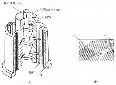
The tool used for honing is a honing head composed of several abrasive strips (whetstones). The abrasive strips around the head can radially expand and contract, and contact the hole surface with a certain pressure. The abrasive strips on the honing head have three types of motion (see Figure 6-2-3 (a)): rotational motion, reciprocating motion, and radial motion with applied pressure. The rotational and reciprocating motions between the honing head and the workpiece cause the abrasive grains of the abrasive strips to form a cross-shaped, non-repeating mesh pattern on the hole surface.
During honing, the abrasive strips cut away a very thin layer of material from the workpiece and form a cross-shaped, non-repeating mesh pattern on the hole surface (see Figure 6-2-3 (b)). This cross-shaped, non-repeating mesh pattern is beneficial for storing lubricating oil, making it easier to form an oil film between the surfaces of the parts, thereby reducing surface wear between the parts.
Characteristics of honing.
- During honing, the contact area between the abrasive grains and the workpiece hole wall is extremely large, and the vertical load of the abrasive grains is only **1/50 to 1/100** of that in ordinary grinding. In addition, the honing cutting speed is low, usually **below 100 meters per minute**, which is only 1/30 to 1/100 of that in ordinary grinding. During honing, the injection of a large amount of cutting fluid can promptly flush away the detached abrasive grains and simultaneously cool the machined surface sufficiently. Therefore, the workpiece generates less heat, is less prone to burning, and the deformed layer is very thin, resulting in a high surface quality.
- Honing achieves high dimensional accuracy, excellent form accuracy, and low surface roughness. The precision of the holes obtained through honing ranges from **IT6 to IT7 grade**, with surface roughness Rα of **0.2 to 0.025 μm**. During honing, the protruding parts of the surface always contact the grinding strip first and are ground away until the strip fully contacts the workpiece surface. This process effectively corrects geometric shape errors left by previous processes, typically reducing hole shape errors to less than 0.005mm.
- The honing head is connected to the machine tool spindle via a floating joint. During operation, the honing head follows the workpiece hole wall as a guide, moving back and forth along the centerline of the pre-machined hole. This mechanism prevents honing from correcting positional errors. Therefore, pre-machining must be performed during the hole finishing process to ensure positional accuracy. Typically, the honing allowance is **0.05-0.08mm** after boring, **0.02-0.04mm** after reaming, and **0.01-0.02mm** after grinding. For larger allowances, two-stage honing (coarse and fine) can be conducted.
- Honing holes offers high production efficiency and short processing time, with a single hole honing taking only 2-3 minutes. It produces excellent machining quality and has a wide range of applications, suitable for machining cast iron, hardened and unhardened steel, and bronze parts. However, it is not suitable for machining tougher non-ferrous metals. The machining hole diameter range is **φ15 to φ500 mm**, and the hole depth-to-diameter ratio can reach over 10.
3. Grinding (Lapping)
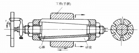
Grinding is a widely used hole finishing method, typically performed after precision boring, reaming, or grinding. The materials, abrasives, and allowance for grinding holes are similar to those used for external cylindrical surfaces. The grinding process for sleeve component holes is illustrated in Figure 6-2-4.
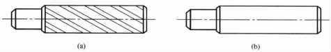
The adjustable grinding bar shown consists of a conical mandrel and a grinding sleeve. By turning the nuts at both ends, the diameter can be adjusted within a specific range. The grinding sleeve features grooves and notches that allow uniform expansion/contraction during adjustment while storing abrasives. Before grinding, the workpiece is mounted on the sleeve, the grinding bar is installed on the lathe, and abrasives are applied. The bar’s diameter is adjusted to apply appropriate pressure on the workpiece before grinding begins. During operation, the grinding bar rotates while the workpiece is manually moved back and forth. Fixed grinding bars are primarily used in single-piece production. Grooved grinding bars (Figure 6-2-5(a)) are ideal for coarse grinding due to their abrasive storage capacity, while smooth grinding bars (Figure 6-2-5(b)) are generally employed for precision finishing.
Grinding has the following characteristics:
- All grinding tools are made of softer materials than the workpiece, including cast iron, copper, bronze, brass alloys, and hardwood. Steel is occasionally used for grinding tools. During grinding, abrasive particles partially suspend between the workpiece and tool while others embed into the tool’s surface layer. As the workpiece and tool move relative to each other, the abrasive material removes a thin metal layer from the workpiece’s surface (primarily from the previous processing stage, removing the protrusions left on the surface of the workpiece).
- Grinding is not only a mechanical process of machining metal with abrasive grains, but also a chemical process. The abrasive mixture (or grinding paste) forms an oxide layer on the surface of the workpiece, which is easily removed by the abrasive, thus greatly accelerating the grinding process.
- The relative motion between the grinding tool and the workpiece is complicated during grinding, so each abrasive grain will not repeat its own motion trajectory on the surface of the workpiece, so it is possible to uniformly cut the convex peaks on the surface of the workpiece.
- As grinding is performed at low speed and low pressure, the workpiece exhibits high surface shape and dimensional accuracy (**IT6 grade or above**), with surface roughness Rα below **0.16 μm**. The roundness and cylindrical accuracy of the holes are correspondingly enhanced, while residual compressive stress and slight work hardening are present. However, this process cannot improve the positional accuracy between workpiece surfaces.
- Manual grinding has a large workload and low productivity. It does not require high precision of machine tools and equipment. Both metal materials (steel, cast iron, copper, aluminum, cemented carbide, etc.) and non-metallic materials (semiconductor, ceramic, optical glass, etc.) can be processed.
- For large holes in shell or cylinder parts requiring grinding, the process can be performed on a drilling machine or modified simple equipment. The grinding bar simultaneously rotates and moves axially, but it must be connected to the machine spindle with a floating connection. Otherwise, if the grinding bar’s axis deviates from the hole’s axis, it will cause shape errors in the hole.
4. Rolling
The principle of internal hole rolling is identical to that of external cylindrical grinding. Due to its high production efficiency, rolling is commonly used as an alternative to honing. After rolling, the internal hole precision is within **0.01mm**, with a surface roughness Rα value of **0.16μm or finer**. Rolling enhances surface strength, improving both surface hardness and wear resistance.
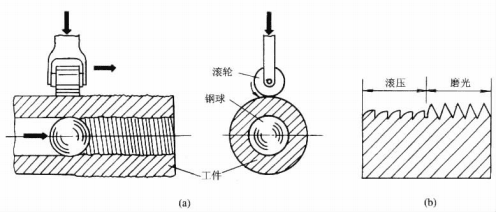
Figure 6-2-6 illustrates a schematic diagram of the rolling process. Rolling can be carried out on ordinary machine tools with rolling devices without special equipment, so it is widely used in production, such as the finishing of live pin holes, cylinder holes and transition arcs of crankshaft necks. Rolling processing is very sensitive to the density and uniformity of soft and hard materials, and the inhomogeneity of materials will seriously affect the quality of rolling.
Figure 6-2-7 depicts a hydraulic cylinder rolling head. The conical rollers 3 on the inner hole surface are mounted on the conical sleeve 5. During rolling, the conical rollers are inclined at 0°30' or 1° to the workpiece, allowing elastic recovery to prevent increased surface roughness of the workpiece hole wall.
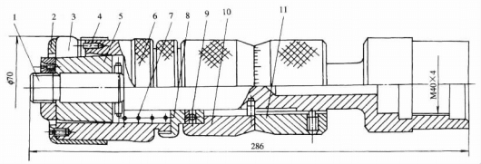
Before performing internal hole rolling, the radial dimensions of the rolling head must be adjusted. The radial size of the rolling head should be determined based on the rolling interference fit of the hole. For general steel materials, the rolling interference fit typically ranges from **0.10 to 0.12 mm**, resulting in a hole diameter increase of **0.02 to 0.03 mm** after rolling. When the rolling head withdraws from the hole in reverse direction after completion, a leftward axial force acts on the conical rollers. This force is transferred to the cover plate, which compresses the spring through the ring and bushing, causing the rolling head to move rightward. This movement reduces the diameter of the rolling head to prevent damage to the already rolled hole wall. Upon complete withdrawal, the rolling head returns to its original position under the spring’s restoring force, reverting the radial dimension to the initial adjustment value. The roll pressure is typically set at a roll speed of **60-80 m/min**, with a feed rate of **0.25-0.35 mm/r**. The cutting fluid consists of **50% sulfurized oil mixed with 50% diesel or kerosene**.
Rolling is a mechanical strengthening process that utilizes freely rotating rollers or balls—previously hardened and precision-polished—to compress workpiece surfaces, thereby enhancing surface quality. This technique reduces surface roughness by **2-3 grades**, increases hardness by **10% to 40%**, and typically improves surface fatigue resistance by **30% to 50%**. The rollers or balls are typically made of high-speed steel or cemented carbide.
(1) Roll Pressing.
Roll pressing is the simplest and most widely used cold working technique. Single-roll pressing requires high and unbalanced pressure, demanding sufficient rigidity in the process system. Multi-roll pressing allows symmetrical arrangement of rollers to press inner holes or outer surfaces, effectively minimizing system deformation. This method also enables the formation of curved or conical surfaces through rolling.
(2) Ball rolling.
This method has a small contact area, high pressure and uniform rolling pressure. It is often used for workpieces with poor stiffness, and can also be made into multi-ball rolling.
Centrifugal rotor rolling.
This method utilizes centrifugal force for rolling. The rolling pressure is determined by the weight of the balls and rollers, the rotor diameter, and rotational speed, typically in direct proportion.
Conclusion
In short, machining the inner hole of sleeve parts requires the right combination of methods, from basic drilling and boring to advanced honing, to meet your specific precision and finish needs.