Basic Knowledge of Cutting Tools,Selection of Cutting Parameters, and Cutting Fluid in CNC Machining
In the world of precision CNC machining, the difference between a flawless component and a costly failure often lies in the fundamentals. A subtle error in tool geometry, a miscalculation in cutting speed, or the wrong choice of cutting fluid can compromise an entire project. As experts dedicated to excellence, we believe that an informed client is the best partner. This guide demystifies the core principles of cutting tools, wear, durability, and parameters to empower you with the knowledge needed to ensure superior quality and efficiency in every part you commission.
Section 1 Geometric angles of cutting tools
I. Composition of the cutting part of the tool
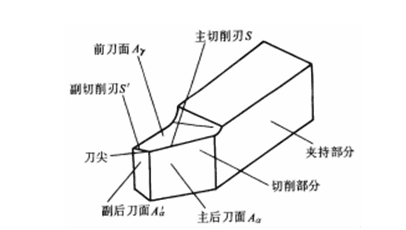
Figure 1-4-1 Structural elements of the cutting part of the lathe tool
The cutting part of a lathe tool can be regarded as the basic form of the cutting part of various tools. Figure 1-4-1 shows the cutting part of a lathe tool, and its structural elements and definitions are as follows:
- Front cutting edge Ay—surface of the cut chip during material removal.
- Main cutting surface Aα —the surface opposite to the transitional surface on the workpiece.
- Secondary rear cutting surface A, α —the surface opposite to the machined surface on the workpiece.
- The main cutting edge S — the intersection line between the front and back cutting surfaces, which performs the primary cutting function.
- Auxiliary cutting edge S, the intersection line between the front cutting face and the auxiliary rear cutting face, which cooperates with the main cutting edge to complete the cutting work and finally form the processed surface.
- The cutting edge at the junction of the main cutting edge and the secondary cutting edge of the blade tip.
II. Geometric parameters of the tool
(1) Defining the Tool Angle Reference Frame
To define the geometric angles of the tool's cutting section, an appropriate combination of reference coordinate planes must be selected as the reference frame. The reference frame used to specify geometric parameters during tool design, manufacturing, grinding, and measurement is called the tool stationary reference frame, as shown in Figure 1-4-2. The reference frame used to define geometric parameters during tool cutting operations is termed the tool working reference frame.
The names, symbols and definitions of the planes of the tool stationary reference frame are shown in Table 1-4-1.
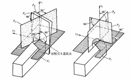
Figure 1-4-2 Tool stationary frame of reference
Table 1-4-1: Planes of the Tool's Resting Reference Frame
| name | symbol | definition |
| cardinal plane | Pr | A plane passing through a selected point on the cutting edge and perpendicular to the direction of the cutting speed at that point |
| cutting plane | Ps | A plane that passes through a selected point on the cutting edge, is tangent to the cutting edge, and is perpendicular to the base plane at that point. |
| Orthogonal plane | Po | A plane selected at the cutting edge, perpendicular to both the base plane and the cutting plane. |
| normal plane | Pn | A plane passing through a selected point on the cutting edge and perpendicular to it |
| Assume a working plane | Pr | Select a point on the cutting edge that is perpendicular to the base plane and parallel to the assumed feed direction |
| tool back plane | Pp | Select a point on the cutting edge that is perpendicular to the base surface and the assumed working plane |
(2) Definition of Tool Angle
The tool angle is a set of angles of the tool in a stationary reference frame. Its name, symbol, and definition are shown in Table 1-4-2. The tool angle of the external cylindrical turning tool is shown in Figure 1-4-3.
Table 1-4-2 Tool Angle Definitions
| Angle name | symbol | definition | |||
| anterior angle | anterior angle | Yo | Definition: Angle between leading face AY and base plane Pr Measure in orthogonal planes | ||
| Front corner | Yn | Measure in the plane of the law | |||
| side rake | Yr | Assume that it is measured in the working plane | |||
| Anterior dorsal angle | Yp | Measure on the back plane | |||
| Angle name | symbol | definition | |||
| relief angle | relief angle Posterior corner Side rear corner Behind the scenes | αo αn αf αp | Definition: The angle between the primary post tool face Aα and the cutting plane Ps Measure in orthogonal planes Measure in the plane of the law Measure in the assumed working plane Measure on the back plane | ||
| tool cutting edge angle | kr | The angle between the primary cutting plane Ps and the assumed working plane P" is measured in the base plane Pr. | |||
| tool angle | εr | The angle between the primary cutting plane Ps and the secondary cutting planes P's is measured in the base plane Pr. | |||
| cutter tilt | λs | The angle between the main cutting edge and the base plane pr is measured in the main cutting plane Ps. | |||
Note: The angles listed in the table are only the angles selected at the main cutting edge (except εr). The corresponding angles selected at the auxiliary cutting edge can be defined by analogy, and a slash " '" is added to the upper right corner of the angle symbol to distinguish it. For example, the auxiliary rake angle of a lathe is kr' and the auxiliary heel angle is αo'.
(3) Tool Angle Conversion.
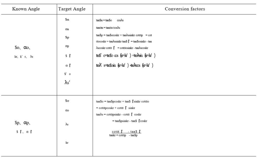
When manufacturing or sharpening tools, it is often necessary to convert tool angles between different coordinate planes. The conversion relationships between these planes are shown in Table 1-4-3.
Table 1-4-3 Conversion relationship of tool angle
III. Tool working Angle
The tool working angle refers to a set of angles defined by the tool in its working reference frame. During cutting operations, the tool's working angle (i.e., the actual cutting angle) differs from its static reference frame angle due to factors like tool installation position and feed motion. Table 1-4-4 provides correction calculations for turning tool working angles under various influencing conditions.
IV. Tool geometry Angle and blade parameter selection
The geometric parameters of a cutting tool's cutting edge significantly influence metal deformation, cutting forces, temperature during machining, workpiece quality, and tool wear. Selecting appropriate tool geometry parameters aims to enhance productivity and reduce production costs while ensuring machining quality and tool durability. Key factors affecting optimal parameter selection include workpiece material, tool material and type, cutting parameters, system rigidity, and machine power. For specific guidance, refer to the content listed in Tables 1-4-5, 1-4-6, and 1-4-7 reference system.
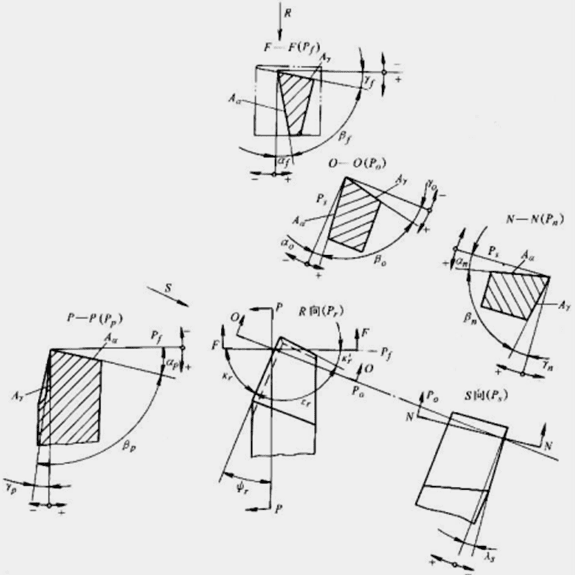
Figure 1-4-3 Tool Angle of External Round Milling Tool
Table 1-4: Revised Cutting Tool Working Angle
| graphic | operating angle |
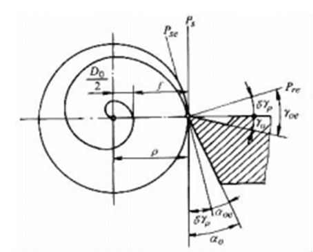 Effect of lateral feed motion on working Angle | Cutting Blade yoe = yo + δyP αoe = αo — δyP 『 In the formula tanδyP = 2πP, '—' denotes feed rate. P—Cutting edge selection point; δyP—Workpiece radius at the cutting edge selection point; P—Back rake angle variation value |
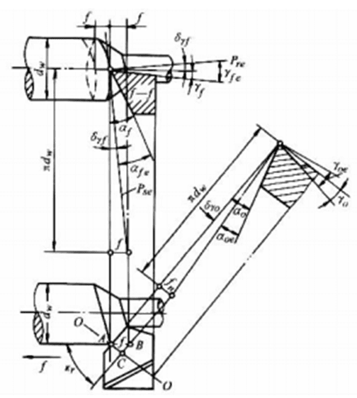 Effect of longitudinal feed motion on working angle of cylindrical cutter | When the right-hand thread is on the left side yoe = yo ± δyo αoe = αo !δyo 『 tanδyo = tanδy『 s,nkr = πdw s,nkr In the formula, the upper symbol applies to the left side of the vehicle thread, while the lower symbol applies to the right side. Right side of the car |
| graphic | operating angle |
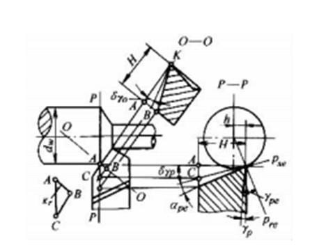 The effect of the tip height on the working angle | In P—P section ype = yp ± δyp αpe = αp dry δyp  In O-O section yoe = yo ± δyo αoe = αo dry δ yo  In this formula, the upper symbol applies to the outer circle of the vehicle, and the lower symbol applies to boring; when the cutting edge is below the working axis, h takes a negative value |
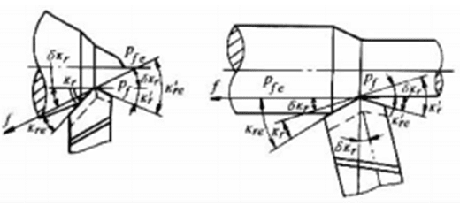 The axis of the tool holder is not perpendicular to the feed direction | kere = kr ± δkr, k're = kr' 干 δkr |
Table 1-4-5 Tool Angle Selection
| Angle name | act on | Key factors to consider when making a choice |
| anterior angle yo | Increasing the front angle can reduce chip deformation and friction resistance, so that cutting force, cutting power and heat generated during cutting are reduced If the front angle is too large, the strength of the cutting edge will be reduced and the heat dissipation volume of the tool head will be reduced, resulting in the reduction of the tool life | For general gray cast iron, select a rake angle of 50° to 150°; for aluminum alloy, choose 30° to 35°; and for general steel, use a rake angle of 10° to 20° with cemented carbide tools. 1) When the bending strength and toughness of tool material are high, a larger rake angle can be taken 2) When the strength and hardness of workpiece material are low and plasticity is good, a larger rake angle should be taken; when processing hard and brittle materials, a smaller rake angle should be taken, or even a negative rake angle 3) For discontinuous cutting or rough machining of cast or forged parts with hard skin, a smaller rake angle should be used; a larger rake angle is recommended for finishing. 4) When the rigidity of the process system is poor or the power of the machine tool is insufficient, a larger rake angle should be taken 5) To minimize tooth profile errors, forming tools and gear tools should adopt a small or even zero rake angle. |
| Angle Name | act on | Key factors to consider when making a choice |
| relief angle αo | The main function of the back angle is to reduce the friction between the tool back face and the workpiece. If the back angle is too large, the strength of the blade will be reduced and the heat dissipation condition will be worse, resulting in reduced tool durability. | For a reasonable rake angle of the cutting tool, when ≤0.25mm/r, αo can be selected as 10° to 12°; when>0.25mm/r, αo should be 5° to 8°. 1) For workpiece materials with high strength and hardness, a smaller rear angle should be adopted; for soft and sticky materials, a larger rear angle is recommended; when processing brittle materials, a smaller rear angle is preferable. 2) For tools with thin cutting layers in precision machining, a larger rake angle is recommended; for rough machining and heavy cutting operations, a smaller rake angle is preferable. 3) When the rigidity of the process system is poor, the rear angle should be reduced appropriately 4) For fixed-size tools such as reamers and taps, a smaller rake angle is recommended to prevent excessive dimensional changes after heavy grinding. |
| tool cutting edge angle kr | A smaller rake angle enhances blade tip strength and extends the effective cutting edge length, which improves heat dissipation and reduces the load per unit blade length, thereby extending tool life. Additionally, reducing the rake angle minimizes the residual surface area on the workpiece. Increasing the main deflection Angle can reduce the back force Fp and increase the inlet force F1, so as to reduce the deformation and vibration of the process system | 1) Under the condition of allowable rigidity of the process system, a smaller principal rake angle should be adopted. When the system has good rigidity (lw/dw <6), kr can be set to 30°-45°; when the system has poor rigidity (lw/dw = 6-12), kr should be 60°-75°; for long slender shafts in turning operations (lw/dw> 12), kr is recommended to be 90°-93°. 2) When processing very hard materials, the main deflection angle should be smaller 3) The value of the principal rake angle should also be adapted to the workpiece's shape. For example, when turning a stepped shaft, a rake angle of kr = 90° is recommended. When using the same tool to turn external surfaces, end faces, and chamfers, a rake angle of kr = 45° is appropriate. |
| end cutting edge angle k’r | A smaller offset angle can reduce the roughness value of the already processed surface of the workpiece and increase the cooling volume of the cutting head, but a too small offset angle will aggravate the friction between the secondary rear cutting face and the already processed surface of the workpiece and easily cause vibration | When the machining system exhibits sufficient rigidity to prevent vibration, the secondary rake angle should be minimized. For precision turning, the recommended range is 5° to 10°, while rough turning requires 10° to 15°. Cutting tools for cutting and slotting operations typically use 1° to 3°. When necessary, precision tools may be ground to achieve a zero-rake angle finishing edge. |
| tool cutting edge inclination angle λs | The blade angle determines the chip flow direction: +λs directs chips toward the workpiece surface, -λs toward the machined surface. Increasing λs can increase the actual working rake angle and reduce the radius of the dull edge, so that the cutting is light and fast A single-edged tool with a large absolute value of- λs allows the cutting edge farther from the tip to contact the workpiece first, protecting the tip from impact. For multi-edge rotary tools, such as cylindrical milling cutters, the helix Angle is the edge inclination Angle, which can make the entry and exit process smooth When the absolute value of- λ increases, the back force Fp will increase significantly | For standard steel and cast iron machining, use λs = 0° to-5° for rough turning without impact loads, and λs = 0° to +5° for finish turning. When impact loads are present, select λs = -5° to 15°; for extreme impact loads, use λs = -30° to-45°. For planers, λs = -10° to-20° is recommended. 1) When the material is hard or has a large impact load, the absolute value should be greater - λs, to protect the blade tip 2) During precision machining, λs should be positive to direct chip flow toward the workpiece surface and maintain a sharp cutting edge. 3) The tool for machining through holes adopts a-λs angle to facilitate chip discharge, while the tool for blind holes uses a +λs angle. 4) When the rigidity of the process system is insufficient, the- λs Angle should be used as little as possible |
Table 1-4-6 Blade Tip Shape Selection
| form | abbreviated drawing | act on | preferences |
| Straight line | 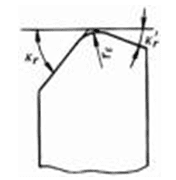 | The use of straight or curved transition edge at the tip can significantly improve the erosion resistance and wear resistance of the tool, and reduce the surface roughness of the workpiece already processed | kr1 = kr bε = 0.5 to 2 mm or bε = (approximately) ap |
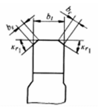 | kr1 = 45o bε = 0.5 to 1 mm or bε = bt | ||
| circular arc | 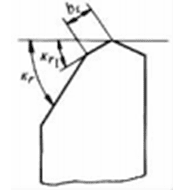 | High speed rigid cutting tool rε = 1 ~ 3mm Ceramic and cemented carbide cutting tools rε = 0.5 ~ 1.5mm Use the smaller value for finishing; use the smaller value when the process system is not rigid enough |
Table 1-4-7 Parameter Selection for Bevels and Blunted Edges
| type | abbreviated drawing | act on | preferences |
| fall arris | 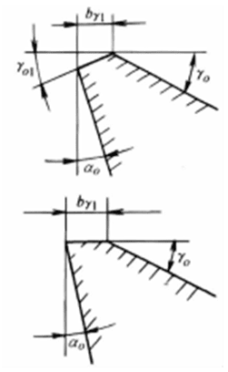 | 1) The primary function of rounded edges and blunt cutting edges is to enhance the cutting edge and reduce tool wear. When performing rough machining or intermittent cutting with hard alloy or ceramic tools, this significantly reduces edge chipping and improves tool durability. 2) The blunt circular blade has a certain amount of cutting and squeezing Irritation and vibration damping effect 3) For precision-cutting tools with minimal feed rates (≤0.2mm/r), tools for processing brittle materials such as cast iron and copper alloys, and tools with complex geometries like forming tools, grinding to create chamfered edges is not recommended. | Typically, b₁ ranges from 0.2 to 1 mm or (0.3 to 0.8) mm. Larger values are used for rough machining, while smaller values are employed for finish machining. Pre-curved front angle: For high-speed steel tools, Ya1 ranges from 0° to 5°; for cemented carbide tools, Ya1 ranges from-5° to-10°. |
| type | abbreviated drawing | act on | preferences |
| Blunt edge | 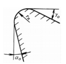 | 1) The main function of chamfer and edge is to enhance the cutting edge and reduce tool damage. When using cemented carbide and ceramic tools for rough machining or intermittent cutting, it has a significant effect on reducing chipping edge and improving tool durability 2) The blunt rounded edge provides additional cutting, squeezing, pressing, and vibration damping functions. 3) For precision-cutting tools with minimal feed rates (≤0.2mm/r), tools for processing brittle materials such as cast iron and copper alloys, and tools with complex geometries like forming tools, grinding to create chamfered edges is not recommended. | Generally, the diameter of heavy-duty cutting is 0.15 mm. The diameter of light-duty cutting is 0.02-0.03 mm; medium-duty cutting is 0.05-0.1 mm; and heavy-duty cutting is 0.15 mm. Heavy-duty cutting is used for heavy-load cutting. |
Section 2 Tool wear
I. Forms of tool wear
Tool wear can be categorized into two main types: continuous gradual wear and two forms of fracture: brittle fracture (including edge chipping, shattering, spalling, and crack fracture) and plastic fracture. There are three fundamental wear patterns (see Table 1-4-8).
Table 1-4-8 Tool wear patterns
| Wear type | explain |
| Rear blade surface wear | The intense friction between the machined surface and the rake face causes wear at the lower edge of the cutting edge on the rake face, forming a wear zone with zero rake angle. This wear pattern typically occurs when machining brittle metals or processing ductile metals with thin cuts and low speeds, such as casting parts, precision-turned steel components, and multi-toothed tools. The wear distribution along the cutting edge's working length shows uneven patterns (see Figure 1-4-4). At the cutting tip (Zone C), where poor strength and heat dissipation occur, wear reaches its maximum (VC). Near the workpiece's outer surface, wear is also significant due to hardened layers from previous operations (VN). The central section (Zone B) exhibits relatively uniform wear, with VB representing the average wear level of the rake face. |
| Front blade surface wear | When machining plastic metal materials, high cutting speeds and thickness create intense friction and elevated temperatures on the rake face. This causes a groove (called a crescent pit) near the main cutting edge, with the highest temperature concentrated at its center. During wear progression, this crescent pit deepens and widens while the cutting edge's strength gradually weakens, ultimately leading to chip breakage. The rake face wear is typically measured by the crescent pit depth (KT). |
| Both the front and back cutting surfaces wear out simultaneously | This type of wear is most common when cutting plastic metals at moderate cutting speeds and feed rates |
II. Causes of tool wear
The main reasons for tool wear are shown in Table 1-4-9.
Table 1-4-9 Tool wear causes
| Wear cause | explain |
| grinding abrasion | Mechanical wear occurs when micro-hard particles (such as carbides, oxides, etc.) and impurities (like sand particles, oxide scale, etc.) on the workpiece surface, along with adhered chip fragments, create grooves on the tool surface. For high-speed steel tools (e.g., reamers, plate cutters, taps) with low cutting speeds and moderate temperatures, this constitutes the primary wear mechanism. |
| Adhesive wear | Under the combined effects of normal pressure between the tool's back face and workpiece surface, as well as between the front face and chips, and cutting temperature, fresh surface contact is formed. When the contact surface reaches interatomic distance, adsorption and adhesion phenomena occur. Adhesive points are gradually sheared or torn away by the workpiece or chips, resulting in adhesion wear on the tool surface. Adhesion wear is one of the primary causes of wear in cemented carbide tools during medium-to-low cutting speeds. |
| Diffuse wear | Under high temperature and pressure, certain chemical elements in tool materials and workpiece materials diffuse into each other in solid state. Specifically, elements like Ti, W, and Co in cemented carbides diffuse into steel, while elements such as Fe and C in workpieces diffuse into tools. This results in reduced hardness and strength of the cutting edge, increased brittleness, and accelerated tool wear. This phenomenon is known as diffusion wear. Diffusion wear is one of the primary causes of tool wear during high-temperature (800-1000°C) cutting operations. Generally, W and Co diffuse faster than Ti and Ta, which explains why YT-class cemented carbides exhibit better high-temperature cutting performance compared to YG-class materials. |
| Phase change wear | When cutting with high-speed steel tools, if the cutting temperature exceeds its phase transition temperature (550 ~ 600℃), the metallographic structure of the tool will change, resulting in reduced hardness and accelerated wear. Therefore, phase transition wear is one of the main reasons for the wear of high-speed steel tools. |
| Chemical wear | At a certain temperature, the medium around the cutting area, such as air, cutting fluid, etc., reacts with the tool material to form some loose and fragile compounds. These compounds are easily carried away by the chips and workpiece abrasion and cause tool wear |
III. Tools wear process and dullness standard
When a cutting tool's wear reaches a critical threshold, it should be discontinued immediately. This wear limit is termed the dullness criterion. As shown in Figure 1-4-5, the typical tool wear progression follows three distinct phases: AB (initial wear phase), BC (normal wear phase), and CD (rapid wear phase). Therefore, replacement should be performed before the rapid wear phase begins.
There are two primary methods for detecting tool wear: direct measurement and indirect measurement. The direct method involves measuring tool wear during non-cutting operations (or through changes in workpiece dimensions), while the indirect method assesses wear by monitoring physical parameters related to the tool during cutting processes, such as cutting forces, vibrations, noise levels, cutting temperature, and surface roughness of machined surfaces.
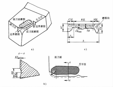
Figure 1-4-4 Typical wear patterns of cutting tools
In actual production, it's impractical to frequently remove tools for wear measurement. Therefore, tool condition assessment relies on observable cutting process indicators. During rough machining, technicians monitor surface brightness changes, observe alterations in chip color and morphology, and detect vibrations or abnormal noises. For precision machining, they evaluate surface roughness variations while verifying dimensional accuracy and shape conformity of processed components.
In experimental evaluations of cutting tool performance, the standard for measuring tool dullness is typically the flank wear depth. The International Organization for Standardization (ISO) specifies that the flank wear zone width VB (see Figure 1-4-4) measured at 1/2 cutting depth serves as the benchmark. However, for automated production tools and preset tools, the radial wear dimension (referred to as radial wear NB) along the workpiece's radial direction is commonly used as the criterion for assessing tool dullness.
The grinding standards differ according to processing conditions. For example, precision machining requires a smaller grinding standard, while rough machining demands a larger one. When the process system has lower stiffness, vibration within the grinding standard must be considered, hence the smaller standard is specified. Similarly, grinding standards are smaller when machining difficult-to-cut materials.
The specific values of the various tool dullness standards can be referred to in the relevant professional manuals.
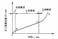
Figure 1-4-5 Typical tool wear process curve
Section 3: Tool durability
I. The relationship between tool durability and cutting parameters
When a cutting tool's wear reaches a critical threshold, it should be discontinued from use. This wear limit is defined as the dullness criterion. The International Organization for Standardization (ISO) has established the wear band width VB measured on the tool surface as the official dullness standard. In practical applications, tool durability serves as an indirect indicator of dullness criteria, enabling more efficient, accurate, and convenient assessment of tool wear conditions.
The total cutting time from the initial operation of a sharpened tool until it reaches the dullness threshold is termed tool life, denoted as T. The product of tool life and the number of sharpening cycles equals the tool's service life, which refers to the cumulative cutting duration from the tool's first use until it becomes unusable.
The influence of cutting parameters on tool durability is highly significant. At present, the mathematical relationship between tool wear durability and cutting parameters can only be obtained by experimental methods.
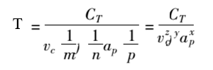
In the formula, CT is the durability coefficient;
m, n, p — indices. These indices vary with cutting parameters, where 0 <m <n <p. This indicates that cutting speed has the greatest influence on tool durability, followed by feed rate, with cutting depth having the least impact. This sequence aligns with their effects on cutting temperature, demonstrating that cutting temperature is the primary factor affecting tool durability.
From Equation (1-4-1) we get
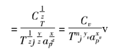
The coefficients Cv and the exponents m, yv, and xv in the formula vary with cutting conditions. This formula enables calculation of permissible cutting speeds for specified parameters 'a, p, and T.
II. The principle of tool durability
There are three methods to determine the reasonable durability of cutting tools: The first method sets durability based on the principle of minimizing individual work hours, known as the maximum productivity durability (Tp). The second method establishes durability according to the lowest cost per workpiece process, termed the minimum cost durability (Tc). The third method determines durability by maximizing profit per unit time, referred to as the maximum profit rate durability (Tpr).
Analysis shows that there is a relationship between these three types of durability, namely Tp <Tpr <Tc. The lowest cost durability is generally used in production, and the highest productivity durability is only selected when the production task is urgent or there is an unbalanced weak link in production.
The following factors should be considered when determining tool durability:
- For tools with simple manufacturing and grinding and low cost, such as turning tools and drills, the durability can be set lower, while for the opposite, the durability should be set higher, such as milling tools, reamers and gear tools.
- For multi-tool machines, combination machines, and automated tooling with complex tool installation, replacement, and adjustment, higher durability is required. For machine-mounted indexable turning tools and ceramic tools, where replacement time is short, lower durability requirements are acceptable.
- For the key process that does not meet the production beat, the durability of this process should be selected lower in order to achieve the balance of workshop production. When the unit time of a certain process is responsible for a large amount of the factory expenditure, the tool durability should also be selected lower.
- When machining large parts, in order to avoid changing the tool in the middle of machining the same surface, the durability should be specified to be higher, at least to complete one pass.
- The tool durability on the production line should be specified for one or two shifts, so that the tool can be changed during shift change.
Table 1-4-10 lists the reasonable durability values of common cutting tools for reference when selecting.
Table 1-4-10 Reference values of reasonable durability of common cutting tools (min)
| Tool type | Durability reference values |
| High speed steel cutting tools, planers, boring tools | 30 ~ 60 |
| Hard alloy indexable turning tools, ceramic tools | 15 ~ 45 |
| carbide-tipped turning tool | 15 ~ 60 |
| carbide end mill | 120 ~ 180 |
| high speed steel bit | 80 ~ 120 |
| Diamond cutting tool for processing non-ferrous metals | 600 ~ 1200 |
| Cubic boron nitride tool for machining quenched steel | 120 ~ 150 |
| Profile cutter | 120 ~ 180 |
| High speed steel drill bit for multi-axis drilling machine | 200 ~ 300 |
| Hard alloy end milling cutter for multi-axis milling machine | 400 ~ 800 |
| cutter of gear wheel | 200 ~ 300 |
| Tools for CNC machine tool machining | On a shift basis |
Section 4: Selection principles of cutting parameters
The determination of cutting parameters involves rationally setting the cutting depth (ap), feed rate (f), and cutting speed (vc) based on the selected tool material and geometric angles.
The reasonable cutting amount refers to the cutting amount which makes full use of the cutting performance of the tool and the performance of the machine tool, and obtains high productivity and low processing cost under the premise of ensuring the processing quality.
Different machining properties require distinct cutting parameters. Therefore, the selection criteria for cutting parameters should vary accordingly. During rough machining, priority should be given to maximizing metal removal rate and ensuring tool durability. Typically, the maximum possible cutting depth (ap) is selected first, followed by a larger feed rate (f), and finally, the appropriate cutting speed (vc) is determined based on tool life requirements. For finish machining, the focus shifts to achieving workpiece accuracy and surface quality. In this case, smaller feed rates (f) and cutting depths (ap) are generally preferred, while higher cutting speeds (vc) are prioritized.
I. Selection of Cutting Depth ap
The depth of cutting should be determined according to the machining allowance of the workpiece.
During rough machining, the tool should remove all material in one pass while retaining sufficient allowance for finish machining. When processing allowances are excessive, the workpiece system exhibits low rigidity, the machine's power is insufficient, tool strength is inadequate, or intermittent cutting causes significant shock vibrations, multi-pass machining may be employed. For cast or forged parts with hardened surface layers, ensure the tool depth (ap) exceeds the thickness of the hardened layer to protect the cutting edge.
The machining allowance of semi-finishing and finishing is generally small and can be cut in one time. But sometimes in order to ensure the machining accuracy and surface quality of the workpiece, a second pass can also be used.
When cutting for many times, the cutting depth of the first cut should be as large as possible, generally 2/3 ~ 3/4 of the total machining allowance.
On medium power machine tools, the cutting depth of rough machining can reach 8 ~ 10mm, the cutting depth of semi-finishing (surface roughness of Ra 6.3 ~ 3.2μm) is 0.5 ~ 2mm, and the cutting depth of finishing (surface roughness of Ra 1.6 ~ 0.8μm) is 0.1 ~ 0.4mm.
II. Selection of feed rate
After determining the cutting depth, the next step is to select the maximum possible feed rate. During rough machining, the choice of feed rate is constrained by several factors due to the significant cutting forces acting on the system: the rigidity of the machine-tool-toothpiece-to-workpiece assembly, the strength of the machine tool's feed mechanism, the machine tool's effective power and torque, as well as blade strength during intermittent cutting operations.
In semi-finishing and finishing, the maximum feed rate is mainly limited by the roughness of the machining surface of the workpiece.
In the factory, the feed rate is generally selected according to the experience according to a certain table (see the relevant tables in the chapters of turning, drilling, milling, etc.). Under the condition of possibility, it can be retrieved and optimized through the cutting database.
III.Selection of cutting speed vc
After ap and " selection, the value of cutting speed vc can be determined by calculation or table lookup under the condition of ensuring reasonable durability of the tool. In the specific determination of vc value, the following principles should generally be followed:
- When rough turning, the cutting depth and feed are large, so the cutting speed is lower; when finishing, the cutting speed is higher.
- When the machinability of the workpiece material is poor, a lower cutting speed should be selected. Therefore, the cutting speed of gray cast iron should be lower than that of medium carbon steel, while the cutting speed of aluminum alloy and copper alloy should be much higher than that of steel.
- The higher the cutting performance of tool materials, the greater the permissible cutting speed. Therefore, cemented carbide tools can achieve several times higher cutting speeds than high-speed steel tools. Furthermore, coated cemented carbide, ceramic, diamond, and cubic boron nitride tools can attain significantly higher cutting speeds compared to cemented carbide tools.
In addition, when determining the cutting speed of finishing and semi-finishing, attention should be paid to avoid the areas where chip deposits and scale spines are generated;
In the case of easy vibration, the cutting speed should avoid the critical speed of self-excited vibration; when machining cast and forged parts with hard skin, large pieces, slender pieces and thin-walled parts, as well as intermittent cutting, a lower cutting speed should be selected.
Section 5: Cutting Fluid
I. The role of cutting fluid
(1) Lubrication Function
Cutting fluid penetrates between the tool, chips, and machined surface to form a thin lubricating film or chemical adsorption layer, thereby reducing friction between them. The lubrication effectiveness primarily depends on the fluid's penetration capability, film-forming capacity, and the strength of the lubricating film. By adding additives with different compositions and ratios to the cutting fluid, its lubrication performance can be optimized.
The lubrication effect of cutting fluid is also related to the cutting conditions. For example, the higher the cutting speed, the greater the cutting thickness, and the higher the strength of the workpiece material, the worse the lubrication effect of cutting fluid.
(2) Cooling Effect
Cutting fluid effectively removes substantial heat from the cutting zone, thereby reducing temperature. Its cooling performance depends on key parameters including thermal conductivity, specific heat capacity, latent heat of vaporization, evaporation rate, flow rate, flow velocity, and operating temperature. Generally, aqueous solutions demonstrate the best cooling efficiency, followed by emulsions, with oil-based fluids performing the least effectively.
(3) Cleaning Effect
The flow of cutting fluid effectively removes fine chips and abrasive particles from both the cutting zone and machine tool guideways, which is crucial for grinding, deep hole machining, and automatic wire EDM processes. The cleaning efficiency of cutting fluid depends on its permeability, fluidity, and operating pressure, while also being influenced by the properties of surfactants.
(4) Anti-rust effect
After adding anti-rust additives to the cutting fluid, a protective film with strong adhesion can be formed on the surface of metal materials, or a passive film can be formed by combining with metal, which can play a good role in anti-rust and anti-corrosion for workpieces, machine tools and tools.
II. Additives in cutting fluid and types of cutting fluid
(1)Additives in cutting fluid
Additives are some chemical substances, which can be divided into oil additives, extreme pressure additives, surfactant additives and other additives.
- Oil-based additives contain polar molecules that form a strong adsorption film on metal surfaces, providing effective lubrication even at low cutting speeds. Common oil-based additives include animal fats, vegetable oils, fatty acids, amines, alcohols, and lipids.
- Extreme Pressure Additives Extreme pressure additives are organic compounds containing sulfur, phosphorus, chlorine, and iodine. When exposed to high temperatures, these additives chemically react with metal surfaces to form a chemical lubricating film that withstands extreme temperatures and pressures. This protective film not only resists high-pressure conditions but also prevents direct metal-to-metal contact, reduces friction, and maintains optimal cutting lubrication.
- Surfactants (Emulsifiers) Surfactants, also known as emulsifiers, serve dual functions: emulsifying mineral oils with water to form emulsions, and providing lubrication through oil-based additives. The former facilitates the mixing of mineral oils and water to create emulsions, while the latter forms a protective lubricating film on metal surfaces. Common surfactants like sodium petroleum sulfonate and sodium oleate soap demonstrate excellent emulsification properties, along with additional benefits such as cleaning, lubrication, and rust prevention.
In addition, there are anti-rust additives (such as sodium nitrite, sodium petroleum sulfonate, etc.), anti-foam additives (such as dimethyl silicone oil) and anti-mold additives (such as phenol, etc.). With the proper selection of additives, a good cutting fluid can be obtained.
- Types of cutting fluid
Cutting fluid mainly has two kinds, water-based and oil-based. The former has strong cooling capacity, and the latter has outstanding lubrication performance.
- The main components of water-based cutting fluid are water, chemically synthesized water or emulsion. Water-based cutting fluid is added with anti-rust agent, and some are added with extreme pressure additives.
- The main components of oil-based cutting fluid are various mineral oils, animal oils, vegetable oils, or composite oils composed of them, and various additives such as extreme pressure additives and oil additives can be added according to needs.
III..Selection and application of cutting fluid
(1) Cutting Fluid Selection
The effect of cutting fluid depends not only on the performance of cutting fluid itself, but also on the material of the workpiece, the material of the tool and the processing method. The selection should be considered comprehensively.
In rough machining and semi-finishing, the cutting heat is large, so the role of cutting fluid should be mainly cooling and heat dissipation. In finishing and super-finishing, in order to obtain good surface quality, cutting fluid should be mainly lubrication.
Hard metal tools have good heat resistance and generally do not need cutting fluid.
Because the cutting of difficult machining materials is in the state of boundary lubrication friction under high temperature and high pressure, it is advisable to use extreme pressure cutting oil or extreme pressure emulsion.
The characteristic of grinding is high temperature, which will produce a large amount of fine chips and sand particles. Therefore, the grinding fluid should have good cooling and cleaning properties, and should have certain lubrication and rust prevention properties.
The selection of cutting fluid under various machining conditions can be referred to in Table 1-4-11.
Table 1-4-11 reference table for selection of cutting fluid
IV. What is the concept of free and non-free cutting, right angle and oblique cutting?
| Workpiece materials | Carbon steel, alloy steel | stainless steel | heat resisting alloy | iron casting | Copper and its alloys | Aluminum and its alloys | ||||||||
| cutter material ① | highspeed steel | hard metal | high speed steel | hard metal | high speed steel | hard metal | high speed steel | hard metal | high speed steel | hard metal | high speed steel | hard metal | ||
| turnery | rough turn | 3、1、7 | 0、3、1 | 7、4、2 | 0、4、2 | 2、4、7 | 8、2、4 | 0、3、1 | 0、3、1 | 3、2 | 0、3、2 | 0、3 | 0、3 | |
| finish turning | 4、7 | 0、2、7 | 7、4、2 | 0、4、2 | 2、8、4 | 8、4 | 0、6 | 0、6 | 3、2 | 0、3、2 | 0、6 | 0、6 | ||
| milling | end milling | 4、2、7 | 0、3 | 7、4、2 | 0、4、2 | 2、4、7 | 0、8 | 0、3、1 | 0、3、1 | 3、2 | 0、3、2 | 0、3 | 0、3 | |
| milling flutes | 4、2、7 | 7、4 | 7、4、2 | 7、4、2 | 2、8、4 | 8、4 | 0、6 | 0、6 | 3、2 | 0、3、2 | 0、6 | 0、6 | ||
| add | drilling | 3、1 | 3、1 | 8、4、2 | 8、4、2 | 2、8、4 | 2、8、4 | 0、3、1 | 0、3、1 | 3、2 | 0、3、2 | 0、3 | 0、3 | |
| Worker | reaming | 7、8、4 | 7、8、4 | 8、7、4 | 8、7、4 | 8、7 | 8、7 | 0、6 | 0、6 | 5、7 | 0、5、7 | 0、5、7 | 0、5、7 | |
| law | tapping | 7、8、4 | 8、7、4 | 8、7 | 0、6 | 5、7 | 0、5、7 | |||||||
| broaching | 7、4、8 | 8、7、4 | 8、7 | 0、3 | 3、5 | 0、3、5 | ||||||||
| Gear hobbing, gear shaping | 7、8 | 8、7、4 | 8、7 | 0、3 | 5、7 | 0、5、7 | ||||||||
| grinding | coarse grind | 1、3 | 4、2 | 4、2 | 1、3 | 1 | 1 | |||||||
| finish grinding | 1、3 | 4、2 | 4、2 | 1、3 | 1 | 1 | ||||||||
Note: The numbers in this table represent the following meanings:
0-cutting 1-chemical synthetic fluid with weak lubrication 2-chemical synthetic fluid with good lubrication 3-ordinary emulsion 4-extreme pressure emulsion 5--ordinary cutting oil 6--kerosene 7--extreme pressure cutting oil containing sulfur and chlorine or composite oil of vegetable oil and mineral oil 8--extreme pressure cutting oil containing sulfur, chlorine, chlorine phosphorus or sulfur chlorine phosphorus.
① The tool material is the grinding wheel during grinding.
(2) Cutting fluid usage method
The commonly used method is the pouring method. Because the cutting fluid flow rate is slow (o <10m/s) and the pressure is low (p <0.05Mpa), it is difficult to penetrate directly into the highest temperature area, so it is only used for the cutting of ordinary metal cutting machine tools. During processing, the cutting fluid should be poured into the cutting area as far as possible.
For deep hole machining, difficult-to-machine materials, and high-speed grinding, high-pressure cooling should be used. The working pressure of cutting fluid during cutting is about 1 ~ 10Mpa, and the flow rate is 50 ~ 150L/min.
Spray cooling is an effective method for cutting fluids, particularly suitable for machining difficult-to-process materials such as turning, milling, broaching, tapping, and hole drilling, as well as for tool sharpening. During machining, the cutting fluid is atomized by compressed air through a spray device and rapidly ejected into the cutting zone.
Conclusion
Mastering the fundamentals—from tool geometry and wear patterns to optimal cutting parameters and fluid selection—is non-negotiable for achieving high-quality results. A deep understanding of these core principles empowers you to optimize durability, enhance precision, and ultimately reduce costs, ensuring the success of every CNC machining project.