Everything You Need to Know About Housing Parts?
Struggling with housing parts that don't fit or fail prematurely? Poor quality casings can stop your entire production line. I will show you how to get durable, precise housing parts every time.
I. What is housing parts ?
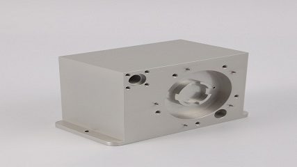
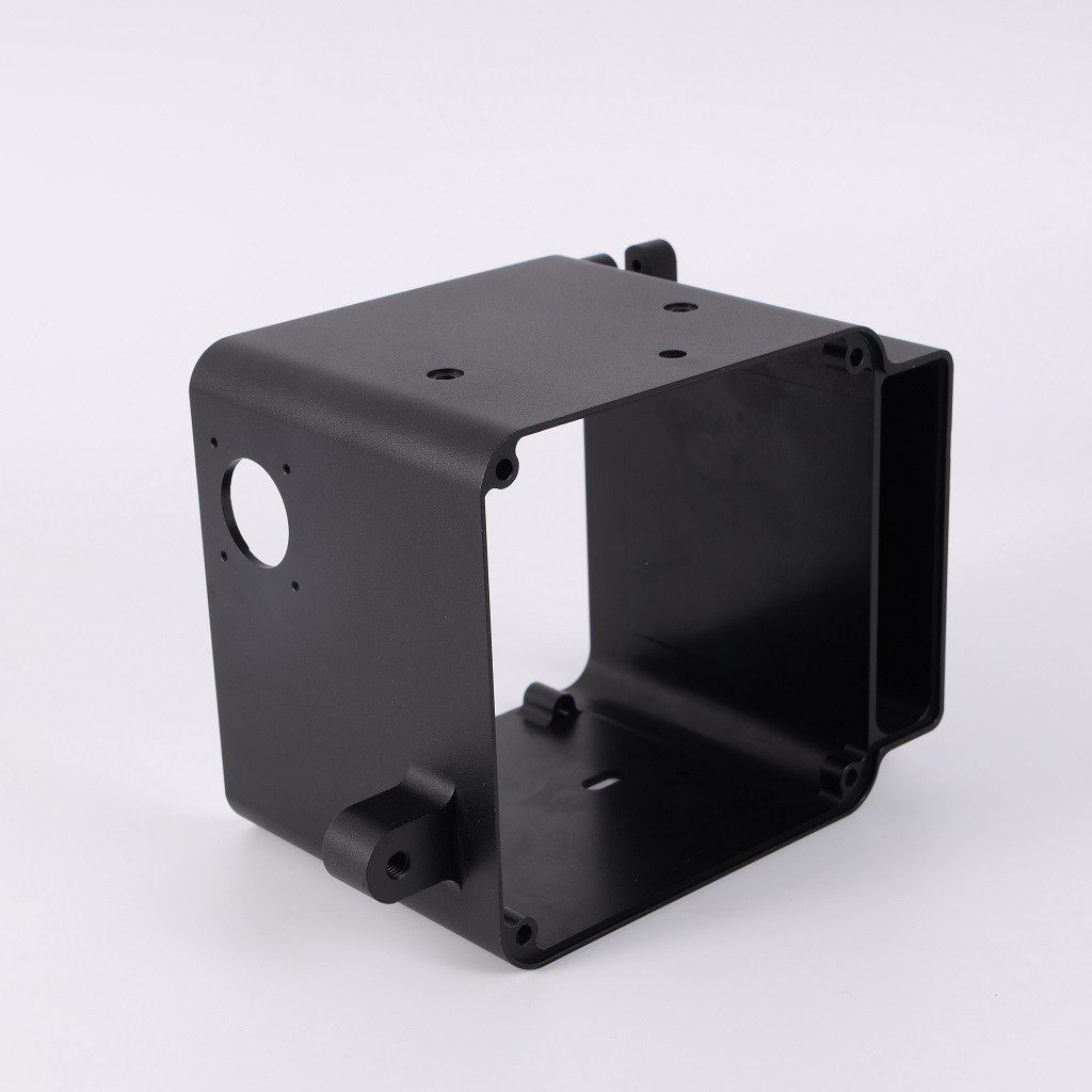
Housing parts are the protective outer shells for mechanical or electronic components. They support internal parts, protect them from damage and contaminants like dust or water, and often help dissipate heat. They are essential for a product's function, longevity, and safety.
Box-shaped parts (housing parts, casing parts) are typical mechanical components, such as lathe headstocks, gearboxes, and transmission housings. These box-shaped parts are core foundational components in mechanical equipment, acting as a "shell" or "base" to install, support, and fix transmission components such as gears, shafts, and bearings. They ensure these components maintain precise relative positions and work together to transmit power and change speed, commonly found in reducers and gearboxes. They require sufficient strength and rigidity to withstand loads, and their design often integrates features such as locating holes and oil passages.
What is the function of housing parts ?
As the foundational components of machinery and equipment, housing parts integrate critical elements like shafts, bearings, bushings, and gears through precise positional relationships, enabling coordinated motion through defined transmission mechanisms. The manufacturing quality of these housing components not only directly determines the assembly accuracy and operational precision of the housing itself, but also significantly impacts the machine's working precision, service performance, and service life.
II. What is the characteristics of housing parts?
Figure 6-3-1 shows a schematic diagram of several common housing parts. As can be seen from the figure, although the shapes and sizes of various housing parts are different, their structures have the following main characteristics:
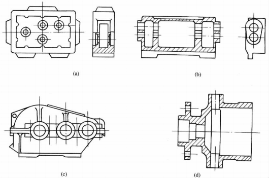
-
Complex Structural Design:
The housing typically serves as the foundational assembly component. The more components installed on it, the more intricate its shape becomes, as installation requires not only positioning surfaces and holes but also screw holes for securing parts. To support components, sufficient rigidity is achieved through complex cross-sectional designs and reinforcing ribs. For lubricant storage, shaped cavities with observation and drainage ports are essential. Additionally, lifting mechanisms like hooks and lug ears are incorporated to facilitate handling and transportation.
-
(2) Large volume:
The box body must be installed and accommodate the relevant parts, so it is necessary to require the boxbody to have a large enough volume. For example, the length of the large reducer housing is 4 ~ 6m, and the width is about 3 ~ 4m.
-
(3) Thin walls prone to deformation:
The large volume and complex shape of the box, combined with the need to reduce weight, typically result in a cavity-type thin-walled structure. However, significant internal stresses during casting, welding, and machining often cause deformation. Improper handling methods during transportation can also lead to deformation.
-
Holes and planes with high precision requirements:
These are mostly bearing support holes and assembly reference planes, which have high requirements in dimensional accuracy, surface roughness, shape and position accuracy. Their machining accuracy will directly affect the assembly accuracy and service performance of the housing. Therefore, in general, when machining the box, not only the machining parts are more, but also the machining difficulty is greater. According to statistical data, the machining time of medium-sized machine tool factories for box parts accounts for about 15% ~ 20% of the total machining time of products.
III. Factors to Considering in making the housing pats:
Figure 6-3-2 shows a schematic diagram of a lathe spindle box. Taking it as an example, it can be summarized into the following five accuracy requirements:
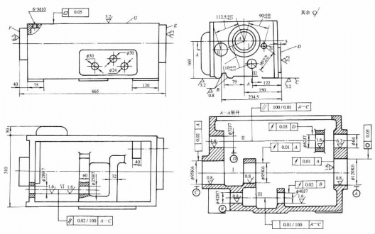
1. Hole Diameter Accuracy:
Dimensional and geometric shape tolerances of the bore can lead to poor bearing-hole fit. An oversized bore with excessive clearance destabilizes the spindle's rotational axis, reduces support stiffness, and increases vibration and noise. Conversely, an undersized bore causes excessive tightness, leading to deformation of the outer ring that prevents proper operation and shortens bearing life. Irregularly shaped bore holes also deform the outer ring, causing radial runout of the spindle. Therefore, strict hole accuracy requirements are essential. The spindle bore's dimensional tolerance grade is **T6**, while other holes use grades ranging from **T6 to T7**. Geometric shape accuracy for holes is not specified but generally maintained within dimensional tolerance limits.
2. Position accuracy of holes:
The coaxiality error of each hole on the same axis and the perpendicularity error of the hole end face to the axis will cause the shaft and bearing to be assembled into the box body, resulting in radial jump and axial movement of the spindle, and aggravating the shaft. The parallelism error between the holes affects the meshing quality of the gears. Generally, the coaxiality of the holes on the same axis is about half of the minimum hole size tolerance.
3. Positional Accuracy of Holes and Planes:
Generally, parallelism requirements must be specified for main holes and the installation base surface of the spindle housing, which determine the positional relationship between the spindle and the bed guide rails. This precision is achieved through scraping during final assembly. To reduce scraping workload, parallelism tolerances between the spindle axis and the installation base surface are typically specified. In both vertical and horizontal directions, only upward and forward deviations at the spindle's front end are permitted.
4. Accuracy of Major Planes:
The flatness of assembly reference surfaces affects the contact stiffness between the spindle housing and machine bed during assembly. When used as positioning references during machining, it impacts the precision of critical holes. Therefore, the bottom surface and guide surfaces must be perfectly flat. Flatness is evaluated by measuring contact area or contact points per unit area using the color coating method. The flatness of the top surface is crucial for ensuring the box cover's sealing integrity and preventing lubricant leakage during operation. When this top surface serves as a positioning reference for hole machining in mass production, its flatness requirements become even more stringent
5. Surface roughness:
The roughness of critical holes and primary planes significantly affects the mating characteristics or contact stiffness of mating surfaces. These specifications are typically evaluated using the Rα value. Generally, the Rα value for spindle holes is **0.4 μm**, while other longitudinal holes require **1.6 μm**. The inner end face of holes should have an Rα value of **3.2 μm**, and assembly/benchmarking surfaces must maintain an Rα value between **0.63 to 2.5 μm**. Other flat surfaces should conform to an Rα value ranging from **2.5 to 10 μm**.
IV. What are the Materials, blanks and heat treatment of casing parts?
Casing components feature intricate internal cavities, requiring materials and manufacturing methods that facilitate molding. Gray cast iron (HT200–HT400) is the preferred choice due to its excellent formability, superior machinability, cost-effectiveness, and outstanding wear resistance with vibration damping properties. While HT200 remains the most widely used grade, precision-critical components such as the spindle housing for coordinate boring machines (Figure 6-3-2) require wear-resistant cast iron. For certain simple machine tool housing components or small-batch/individual-piece production parts, steel plate welding structures can be employed to shorten the blank manufacturing cycle and reduce costs. Heavy-duty housing components may sometimes utilize cast steel blanks according to design requirements. Under specific conditions, aluminum-magnesium alloy or other aluminum alloys can be used to manufacture housing blanks for weight reduction purposes, such as in aviation engine housings.
Materials and Blanks
The precision and machining allowance of cast blanks are determined by production batch size. For single-piece or small-batch production, wooden molds are typically used for manual shaping. These blanks exhibit lower precision and require larger machining allowances, with flat surface allowances generally ranging from **7 to 12mm** and radial hole allowances from **8 to 14mm**. In mass production, metal molds are commonly employed for machine shaping. This method achieves higher precision with reduced machining allowances, typically **5-10mm** for flat surfaces and **7-12mm** for radial holes. To minimize machining allowances, pre-drilled holes with diameters exceeding 50mm in single-piece/small-batch production and holes over 30mm in batch production are generally cast into the blanks. Additionally, during casting, care should be taken to prevent sand holes and porosity. The wall thickness of housing components should be kept as uniform as possible to reduce residual stresses during blank manufacturing.
Heat Treatment (Aging)
Heat treatment is a critical process in the machining of housing components, requiring meticulous planning. Given the complex structure and uneven wall thickness of these parts, significant residual stresses are generated during casting. To eliminate these stresses, minimize post-processing deformation, and ensure dimensional stability, **manual aging treatment** must be performed after casting. The standard aging procedure specifies: heating to **500-550°C**, holding at this temperature for **4-6 hours**, cooling at a rate of $\le$**30°C/h**, and maintaining the final temperature $\le$**200°C**. For box-type components with general precision requirements, manual aging treatment is typically performed after casting. High-precision or complex-shaped components require additional aging after rough machining to eliminate residual stresses caused by initial processing. For parts with lower precision demands, aging treatment is sometimes omitted. Instead, manufacturers utilize the downtime between rough and finish machining processes to allow **natural aging** through prolonged storage and transportation. In addition to the heating and insulation method, the **vibration aging method** can also be used to eliminate the residual stress of the box parts.
V. What are the machining method of housing parts?
The machining of housing components primarily involves planar and hole processing.
Planar Machining
Planar machining employs various methods including rough-sanding-precision-sanding, rough-sanding-semi-precision-sanding-polishing, rough-milling-precision-milling, or rough-milling-polishing (divided into rough and precision grinding). As planing has low productivity, it is mainly used for small to medium batch production. Milling, being more efficient than planing, is preferred for medium to large batches. For larger production runs, combined milling and grinding methods can be applied to simultaneously perform multi-edge and multi-sided milling or grinding on all surfaces of housing components.
Shaft Hole Machining
Shaft hole machining follows two approaches: rough boring (expansion)-precision boring (reaming) or rough boring (drilling, expansion)-semi-precision boring (rough reaming)-precision boring (precision reaming). For high-precision shaft holes (e.g., spindle holes) requiring **IT6 accuracy** with surface roughness $R_{\alpha}
Conclusion
In short, housing parts are vital engineered components. Success depends on the right material, precise manufacturing, and a clear understanding of the part's function to ensure product reliability and performance.