What Equipments for machining outer cylindrical surface
Getting a perfect cylindrical surface is crucial. The wrong equipment causes flaws, delays, and budget overruns. Let's look at the key tools you need to get it right.
Machining an outer cylindrical surface primarily requires a lathe, along with specific cutting tools like welded or replaceable indexable inserts. For higher precision and smoother finishes, a cylindrical grinder is essential. A reliable lathe fixture also securely holds the workpiece.
So, let's break down these components one by one, starting with the very tip of the spear: the cutting tool itself. Are you using the best tool for your job?
一 Welded cutting tool and replaceable cutting tool
1. Welded carbide cutting tool
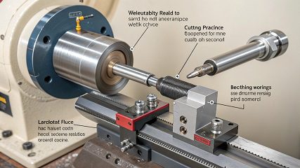
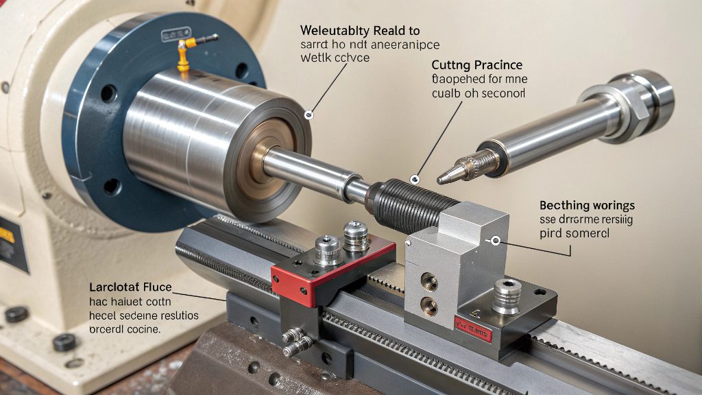
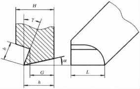
A cemented carbide welded turning tool is fabricated by welding a carbide insert to a structural steel shank. This design offers advantages including simple construction, ease of manufacture, excellent tool rigidity, and operational flexibility, making it widely adopted. Figure 6-1-14 illustrates such a welded turning tool.

Figure 6-1-14 Welded cutting tool
(1)Blade Model Selection.
In addition to selecting appropriate materials and grades, proper model selection is crucial for cemented carbide blades. Table 6-1-1 provides examples of welding blades. Welding-type turning tools are categorized into five types: A, B, C, D, and E. The blade model consists of one letter and one or two digits, where the letter indicates the blade shape and the digits represent the main dimensions.
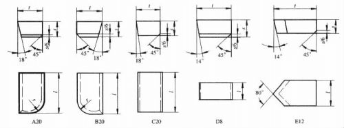
Table 6-1-1 Example of cemented carbide welding blade (GB5244-1985)
| Model | Basic size /mm | Main application | |||
|---|---|---|---|---|---|
| l | t | s | r | ||
| A20 | 20 | 12 | 7 | 7 | Straight outer cylindrical lathe tool, end face lathe tool, left-hand hole turning tool |
| B20 | 20 | 12 | 7 | 7 | |
| C20 | 20 | 12 | 7 | External cylindrical turning tool (KR | |
| D8 | 8.5 | 16 | 8 | ||
| E12 | 12 | 20 | 6 | Finishing tool, thread cutting tool | |
The length (l) in blade dimensions should be determined based on the depth of cut and rake angle. For external cylindrical lathes, the working cutting edge length should not exceed 60% to 70% of the blade length. When selecting blades for cutting tools or grooving tools, the length (l) should be determined by the groove width or cutting tool width. For cutting tools, the length can be estimated using the formula l = 0.6d (where d represents the workpiece diameter). The thickness (t) in blade dimensions should consider factors like regrinding frequency and the structural dimensions of the tool head. The width (s) in blade dimensions should be determined based on factors such as cutting force magnitude.
(2) Shape and dimensions of the cutting slot.
Figures 6-15 illustrate common cutting slot configurations. Open slots feature simplified manufacturing with reduced welding area, ideal for C-type and D-type blades. Semi-closed slots ensure stronger blade bonding through welding, though their processing complexity limits their use to A-type and B-type blades. Enclosed slots maximize welding area but require advanced manufacturing techniques, making them suitable for E-type blades. Notably, notched slots are employed in groove-cutting and cutting tools, providing robust welding performance while maintaining E-type blade specifications despite their intricate production process.
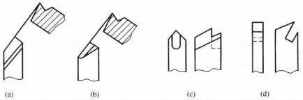
Figure 6-1-15 Blade groove form
(a) open type; (b) semi-closed type; (c) closed type; (d) incision type
The blade groove dimensions should match the blade size. To facilitate sharpening, the blade should extend 0.5 to 1 mm beyond the groove. The rear angle α og of the groove should be 20 to 40 degrees larger than the tool's rear angle α og, as shown in Figure 6-1-16.
(3) The shape and dimensions of the tool holder and cutting head.
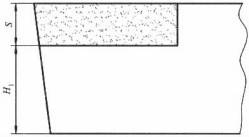
The cross-sectional dimensions of the tool holder are typically determined based on the machine tool's center height. The ratio between the support section height H1 and blade thickness S should be properly proportioned. As shown in Figure 6-1-17, when H1/S> 3, the tensile stress induced by the welded blade surface becomes insignificant, reducing crack formation risks. Conversely, when H1/S <3, the tensile stress in the blade surface layer increases significantly, making cracks more likely to occur.
The blade length can be estimated as six times the blade height (H), with standard sizes such as 100,125,150, and 175 mm being commonly used. Blade heads are typically available in two types: straight and curved. Straight heads are easier to manufacture, while curved heads offer better versatility. The main dimensions of the blade head include
The effective length L and tool tip offset m are illustrated in Figure 6-1-18. These parameters can be calculated using the following formulas: m> l coskr or (B-m)> t cosk'r. The effective length L and tool tip offset m are illustrated in Figure 6-1-18. These parameters can be calculated using the following formulas: m> l coskr or (B-m)> t cosk'r. 45-degree chamfering tool with m> tcos45o 45-degree chamfering tool with m> tcos45o 90° external cylindrical lathe tool, where m ≈ B/4 and L = 1.2 l 90° external cylindrical turning tool, where m ≈ B/4 and L = 1.2 l Cutting edge length m ≈ L/3; L> R (workpiece radius) Cutting edge length m ≈ L/3; L> R (workpiece radius)
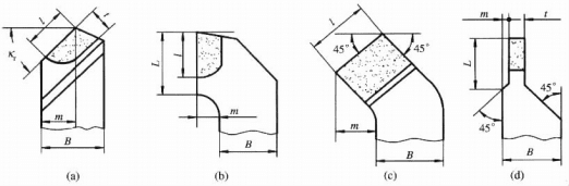
Figure 6-1-18 Shape and size of commonly used cutting tool head (a) straight shank cutting tool; (b) 90° external cylindrical cutting tool; (c) 45° elbow cutter; (d) cutting cutter
2. Indexable turning tool
(1) Characteristics of Indexable Turning Tools.
Indexable turning tools are designed with a mechanical clamping mechanism that secures the indexable insert within the tool slot. When a cutting edge becomes dull, the clamping mechanism is released, allowing the insert to be rotated through a specific angle to replace the worn edge. After re-clamping, the tool can resume cutting operations. Compared to welded turning tools, these tools exhibit the following distinctive features:
- The blade is not welded, no thermal stress, can give full play to the performance of the tool material, high durability;
- Blade replacement is fast and convenient, which can save auxiliary time and improve productivity;
- The knife rod can be used repeatedly to reduce the cost of the knife;
- Can use coated blade, ceramic blade, cubic boron nitride and diamond composite blade;
- The structure is complex, the processing requirements are high, and the one-time investment cost is large;
- It can not be sharpened at will by the user, and the use is not flexible.
(2) Indexable inserts.
Figure 6-1-19 shows an example of indexing insert labeling. Each model has 10 codes, with the first 7 digits required for any model. Regardless of whether the 8th or 9th digit exists, the 10th digit must be separated from the preceding digits by a hyphen "—", as shown in the example.
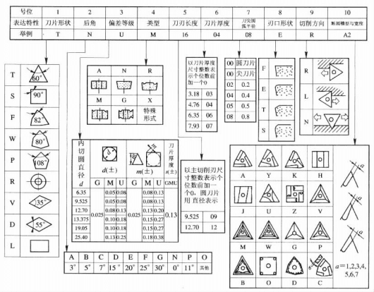
Figure 6-1-19: Example of marking a convertible lathe tool insert
Position 1 indicates the blade shape. The most commonly used are the triangular blade (T) and square blade (S), while the diamond-shaped blades (V and D) are suitable for profiled and CNC machining.
Position 2 indicates the rear corner of the blade. 0. The rear corner (N) is the most commonly used.
Position 3 indicates blade precision, which is divided into 11 grades, with U representing the standard grade and M being the most commonly used medium-grade.
Position 4 denotes blade structure, typically featuring either perforated or non-perforated designs, depending on the clamping mechanism employed.
Position 5 to position 7 represent the cutting edge length, blade thickness, and tip radius, respectively.
Position 8 indicates the blade type. For example, F stands for a sharp blade, which can be omitted if no special requirements apply.
Position 9 indicates the cutting direction. R stands for right cutting blade, L for left cutting blade, and N for both left and right.
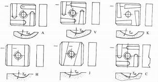
Position 10 indicates the chip breaker groove type and width. Table 6-1-2 lists the characteristics and applications of chip breaker groove types for commonly used indexable turning tool inserts.
Table 6-1-2: Characteristics and Applications of Chip Breaker Grooves for Common Indexable Cutting Tools
| name | Trough code | Blade Angle | Features and applications | ||
|---|---|---|---|---|---|
| ynb | #nb | 入nb | |||
| straight channel | A | 200 | 00 | 00 | The width of the slot is equal at both the front and back. It is used for turning and boring of external cylindrical surfaces where the cutting parameters remain relatively constant. |
| External slits | Y | 200 | 00 | 00 | The tool has a wider front and narrower back, making the chips break easily. It is suitable for medium depth of cut. |
| Inward Slit | K | 200 | 00 | 00 | Narrow at the front and wide at the back, with a wide chip breakage range. Suitable for semi-finishing and rough machining. |
| Direct slot | H | 200 | 00 | 00 | Wide application range. Suitable for 45-degree elbow turning tools and high-volume cutting operations. |
| External slanting groove | J | 200 | 00 | 00 | Features Y and H patterns with excellent chip-breaking performance |
| Right angle | C | 200 | 00 | 00 | Increase the blade tilt angle to reduce back force. This is used when the system rigidity is poor. |
(3) The positioning and clamping mechanism of the indexable turning tool should meet the requirements of correct positioning, reliable clamping, convenient loading and unloading, and simple structure.
① Lever Clamping Mechanism: As shown in Figure 6-1-20. Tightening the clamping screw 5 causes lever 1 to swing, pressing the blade against two positioning surfaces for secure clamping. Blade pad 2 is positioned via spring sleeve 8, while adjustment screw 7 regulates spring 6's tension. This lever clamping mechanism offers high positioning accuracy, reliable clamping, and user-friendly operation, though its structure is relatively complex.
② Wedge-type clamping mechanism: As shown in Figure 6-1-21. Tighten screw 4, and the wedge 5 pushes the blade 3 against the cylindrical pin.
③ Threaded eccentric clamping mechanism: As shown in Figure 6-1-22. The blade is clamped by the eccentric shaft at the upper part of the threaded eccentric pin 1. The mechanism has a simple structure, but the positioning accuracy is not high, requiring the blade to have high precision.
④ Press-hole clamping mechanism: As shown in Figure 6-1-23. Tighten the countersunk screw 2 to clamp the blade using its inclined surface. This mechanism features a simple structure and a compact blade head, making it suitable for small tools.
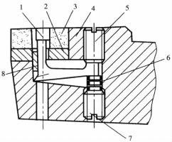
Figure 6-1-20 Lever clamping mechanism 1-Lever 2-Blade Pad 3-Blade 4-Handle 5-Compression screw 6-Spring 7-Adjustment screw 8-Spring Sleeve
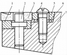
Figure 6-1-21 Wedge clamping mechanism 1-Blade cushion 2-Cylindrical pin 3-Blade 4-Tightening screw 5-wedge 6-spring washer 7-knife handle
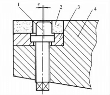
Figure 6-1-22 Threaded Eccentric Clamping Mechanism 1-Eccentric Pin 2-Blade 3-Blade Pad 4-Blade Handle
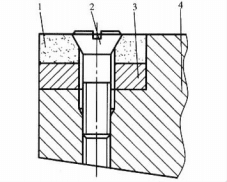
Figure 6-1-23 Press hole clamping mechanism 1-Blade 2-countersunk screw 3-blade washer 4-blade handle
⑤ Upper-press clamping mechanism: As shown in Figure 6-1-24. Tighten screw 5, and the pressure plate 6 will clamp the blade. The upper-press clamping mechanism provides reliable clamping, but the cutting chips may scratch the clamping components.
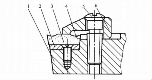
Figure 6-1-24 Upper pressure clamping mechanism
1-Blade handle 2-Blade pad 3, 5-Screws 4-Blade 6-Pressure plate
⑥ Pull-pad clamping mechanism: As shown in Figure 6-1-25. Tighten screw 3 to move pull-pad 1, and the round pin on pull-pad 1 will clamp the blade. The pull-pad clamping mechanism is reliable, but the blade head part has poor rigidity.
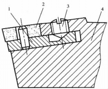
Figure 6-1-25 Pad-type clamping mechanism
1-Pad 2-Blade 3-Screw 4-Handle
The blade holder is made of high-strength steel and has a hardness of ≤50HRC after heat treatment. A blade pad is recommended between the holder and blade to extend its service life. The dimensions of the blade holder may vary slightly depending on the manufacturer. The dimensions of the cemented carbide blade are shown in Table 6-1-3.
Table 6-1-3 Abrasion-resistant carbide blade size
Blade Type |
Figure |
Blade size | |||
|---|---|---|---|---|---|
| d/mm | s/mm | d1/mm | r/mm | ||
| Regular Triangle Hollow cutting tool 3K | 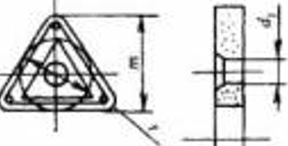 |
10 13 16 |
4 .5 5 .5 7 .0 |
4 .2 5 .2 6 .2 |
0 . 2/14 .08、0 . 5/14 .50、1 . 0/14 .00 0 . 5/19 .00、1 . 0/18 .50、1 . 5/18 .00 1 . 0/23 .00、1 . 5/22 .50 |
| Convex Triangle Hollow cutting tool Sheet T3K | 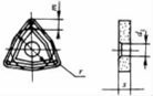 |
13 16 19 |
4 .5 5 .5 7 .0 |
5 .2 6 .2 7 .2 |
0 . 2/3 .50、0 . 5/3 . 33、1 . 0/3 .06 0 . 5/4 . 17、1 . 0/3 . 89、1 . 5/3 .61 1 . 0/4 .72、1 . 5/4 .45、2 . 0/4 .17 |
| Square Hollow cutting tool 4K video | 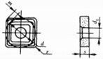 |
10 13 16 19 |
3 .5 4 .5 5 .5 7 .0 |
4 .2 5 .2 6 .2 7 .2 |
0 . 2/1 .99、0 . 5/1 . 86 0 . 2/2 . 61、0 . 5/2 .49、1 . 0/2 .28 0 . 5/3 . 11、1 . 0/2 .90、1 . 5/2 . 69 1 . 0/3 .52、1 . 5/3 . 31、2 . 0/3 . 11 |
| Regular Pentagon Hollow cutting tool 5K | 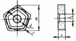 |
16 19 |
4 .5 5 .5 |
6 .2 7 .2 |
1 . 2/17 . 65、1 . 5/17 .54 1 . 5/20 . 89、2 . 0/20 .77 |
| 3H rear-curved triangular milling cutter | 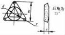 |
6 8 10 |
2 .8 2 .8 3 .5 |
- | 0 . 2/8 . 80 0 . 2/11 . 80、0 . 5/11 .50 0 . 5/14 .50、1 . 0/14 .00 |
| Square four-sided tool with rear corner 4H | 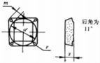 |
8 10 13 |
2 .8 2 .8 3 .5 |
- | 0 . 2/1 .57 0 . 2/1 .99、0 . 5/1 . 86 0 . 5/2 .49、1 . 0/2 .28 |
| Reverse R-Curve Blade R4 | 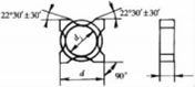 |
10 13 16 |
3 .5 4 .5 5 .5 |
7 .5 10 13 |
Connection arc radius: 1 .9、2 .2 2 . 8、3 .7、4 . 6 5 . 6、6 .5 |
| A2K profiled cutting insert | 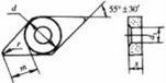 |
13 16 |
4 .5 5 .5 |
5 .2 6 .2 |
0 . 5/6 .99、1 . 0/6 .41、1 . 5/5 . 83 1 . 0/8 . 16、1 . 5/7 .58、2 . 0/6 .99 |
一 Grinding Wheel
1. Organizational elements of the grinding wheel
(1) Abrasives.
Abrasives are classified into two main categories: natural and synthetic. Natural abrasives typically contain more impurities and have uneven texture. Although natural diamond is superior, its high cost makes synthetic abrasives the primary choice today. Their performance characteristics and applications are detailed in Table 6-1-4.
Table 6-1-4 Grinding wheel structural elements, codes, performance and scope of application
| department | name | code name | function | scope of application |
|---|---|---|---|---|
| boule | brown alumina white fused alumina Corundum single alundum black corundum microcrystalline fused alumina |
A WA PA SA BA MA |
Brownish, low hardness, good toughness White, harder than A, sharp abrasive, poor toughness; rose red, better toughness than WA Yellowish-white or white, higher hardness and toughness than white corundum, black, granular, high compressive strength, high toughness The color is similar to brown corundum, high strength, high toughness |
Carbon steel, alloy steel, cast iron Tempered steel, high speed steel, alloy steel High-speed steel, stainless steel, tool sharpening Stainless steel, high vanadium high speed steel heavy load grinding ingot Stainless steel, bearing steel, high speed grinding |
| carbide | black silicon carbide green silicon carbide |
C GC |
Black and glossy, harder than jade, good thermal conductivity, poor toughness Green with a gloss |
Cast iron, brass, non-metallic materials Hard alloy, gemstone, optical glass |
| Superabrasives | artificial diamond cubic boron nitride |
MBD、 RVD class CBN |
White, light green or black, highest hardness, poor heat resistance Brown-black, with a hardness second only to MBD and better toughness than MBD |
Hard alloy, gemstone, ceramic High speed steel, stainless steel, heat resistant steel |
(2) Particle size.
Particle size refers to the size of abrasive particles.
Grain size is classified through two methods: For larger abrasive particles (used in grinding wheels), the classification is determined by the number of sieve holes per inch of screen length. For example, the 46# grade indicates particles that can barely pass through a 46-hole/inch (1 inch ≈2.54 cm) sieve. For finer abrasive particles (called micro-powder, used in grinding), the classification is indicated by adding the letter W before the maximum particle size (in μm). Common grinding wheel grit numbers and their applications are listed in Table 6-1-5.
Table 6-1-5 Abrasive Wheel Grain Size and Application Scope
| class | Grain size | scope of application | |
|---|---|---|---|
| abrasive particle | coarse grain | 8 # 、10 # 、12 # 、14 # 、16 # 、20 # 、22 # 、24 # | snagging |
| medium-grain | 30 # 、36 # 、40 # 、46 # | General grinding. The surface roughness Rα can reach 0.8 μm. | |
| fine stuff | 54 # 、60 # 、70 # 、80 # 、90 # 、100 # | Semimilling, precision milling, and forming grinding. The surface roughness Rα of the workpiece can reach 0.8 to 0.1 μm. | |
| atom | 120 # 、150 # 、180 # 、220 # 、240 # | Finishing, precision grinding, super precision grinding, forming grinding, tool sharpening, honing | |
| micro mist | W60、W50、W40、W28、W20、W14、W10、W7、 W5、W3 .5、W2 .5、W1 .5、W1 .0、W0 .5 | Grinding, precision grinding, super precision grinding, honing, thread grinding, ultra-precision grinding, mirror grinding, and fine grinding can achieve surface roughness Rα of 0.5 to 0.1 μm. | |
(3) Bonding agent.
The bonding agent's properties determine the grinding wheel's strength, impact resistance, corrosion resistance, and heat resistance. Additionally, it affects grinding temperature and surface quality. The types, codes, properties, and applications of bonding agents are listed in Table 6-1-6.
Table 6-1-6 Performance and application range of common binders
| anchoring agent | codename | function | scope of application |
|---|---|---|---|
| pottery and porcelain | V | Heat and corrosion resistant, high porosity, easy to maintain the profile, poor elasticity | Most commonly used for all types of grinding operations |
| resin | B | Higher strength than V, good elasticity, poor heat resistance | Suitable for high speed grinding, cutting, grooving, etc |
| rubber | R | Higher strength than B, more elastic, low porosity, poor heat resistance | Suitable for cutting, grooving and grinding without center |
| bronze | Q | High strength, good conductivity, low wear, poor self-sharpening | For diamond grinding wheels |
(4) Hardness.
The hardness of a grinding wheel refers to the bond strength of the abrasive particles adhered to the bonding agent, as well as the ease with which the particles detach from the wheel surface under grinding forces. A hard grinding wheel means the abrasive particles are firmly bonded and resistant to detachment, while a soft grinding wheel indicates weak adhesion and easy detachment.
The hardness of a grinding wheel significantly impacts both grinding efficiency and surface quality. When the wheel is too hard, dulled abrasive grains remain stuck, resulting in low efficiency, rough surfaces, and potential overheating. Conversely, a soft wheel allows grains to shed easily after dulling, accelerating wear, compromising shape retention, and affecting workpiece quality. The ideal hardness ensures that dulled grains detach automatically as grinding force increases, exposing fresh abrasive particles. This self-sharpening property enhances efficiency, improves surface finish, and reduces wear. The hardness classification of grinding wheels is detailed in Table 6-1-7.
Table 6-1-7 Abrasive wheel hardness classification
| grade | ultra-soft | soft | Soft | centre | Medium hard | hard | superhard | |||||||||
|---|---|---|---|---|---|---|---|---|---|---|---|---|---|---|---|---|
| code name | D | E | F | G | H | J | K | L | M | N | P | Q | R | S | T | Y |
| select | Grinding unhardened steel uses L to N, grinding quenched alloy steel uses H to K, high surface quality grinding uses K to L, and grinding cemented carbide tools uses H to L. | |||||||||||||||
(5) Structure.
The structure refers to the volume ratio of abrasive particles, binder, and pores in a grinding wheel. Based on the percentage of volume occupied by abrasive particles (i.e., particle content), grinding wheels are classified into structure numbers ranging from 0 to 14, as shown in Table 6-1-8. Higher structure numbers indicate a looser structure, making the wheel less prone to chip clogging. This allows cutting fluid and air to penetrate the grinding zone, reducing temperature in the area, minimizing deformation and burn damage caused by heat, and improving grinding efficiency. However, higher structure numbers make it harder to maintain the wheel's profile shape, leading to reduced precision in profile grinding and a relatively rougher surface finish.
Table 6-1-8 Abrasive wheel grit size
| Organization ID | 0 | 1 | 2 | 3 | 4 | 5 | 6 | 7 | 8 | 9 | 10 | 11 | 12 | 13 | 14 |
|---|---|---|---|---|---|---|---|---|---|---|---|---|---|---|---|
| Grain size (%): | 62 | 60 | 58 | 56 | 54 | 52 | 50 | 48 | 46 | 44 | 42 | 40 | 38 | 36 | 34 |
2. Wheel shape, size and marking
To meet the needs of grinding workpieces of various shapes and sizes on different types of grinding machines, there are many shapes and sizes of grinding wheels. The shapes, codes and uses of commonly used grinding wheels are shown in Table 6-1-9.
Table 6-1-9 Shape, code and use of commonly used grinding wheels
| code name | name | section configuration | shape dimension | main application |
|---|---|---|---|---|
| 1 | flat grinding wheel | 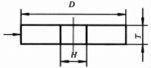 |
1 — D × T × H | Grinding outer cylindrical surfaces, internal holes, flat surfaces, and tool sharpening |
| 2 | cylinder grinding wheel | 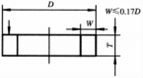 |
2 — D × T — W | End-polish flat |
| 4 | Double-flanged grinding wheel | 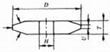 |
4 — D × T/U × H | Gear and thread grinding |
| 6 | Ring sander | 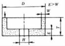 |
6 — D × T × H — W, E | Grind the flat surface and sharpen the back of the tool |
| 11 | taper cup wheel | 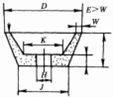 |
11 — D/J × T × H — W,E,K |
Grind the flat surface and sharpen the back of the tool |
| 12a | Disc No.1 grinding wheel | 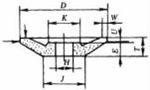 |
12a — D/J × T/U × H — W,E,K |
Sharpen the blade |
| 41 | disc wheel | 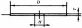 |
41 - D × T × H | Cut and grind |
Note: The ↓ indicates the basic working surface.
The grinding wheel's specifications are marked on its end face in the following order: shape, diameter, abrasive type, grit size, hardness, grain structure, binder, and maximum linear speed. For example, a flat-shaped grinding wheel with a 600mm outer diameter, 75mm thickness, 203mm bore diameter, white corundum abrasive, grit size 54, ultra-hard hardness, grain structure No.8, resin binder, and maximum working linear speed of 60 m/s is designated as Grinding Wheel 1-600 × 75 × 203-WA54Y8B-60.
一 Lathe fixture
Lathe fixtures are specialized devices designed for securing workpieces on various machine tools, including lathes and internal/external cylindrical grinders. These fixtures are mounted on the machine's spindle to ensure precise alignment between the workpiece's machining surface and its reference datum. During design, engineers must consider both the mounting configuration on the spindle and rotational balance requirements, while prioritizing safety measures such as preventing protruding edges (by installing protective covers). Given the cantilevered nature of these fixtures mounted on the spindle, designers should aim to minimize their weight and shorten the cantilever length as much as possible.
1. Classification and structural forms of lathe fixtures
The lathe fixture can be roughly divided into spindle type, angle iron type and flower plate type.
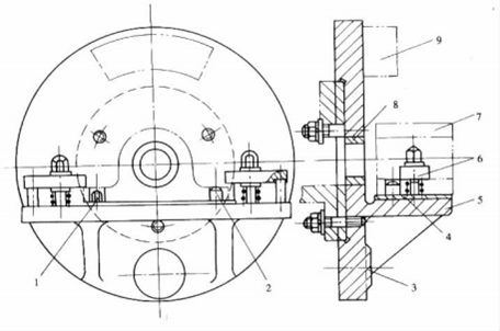
Figure 6-1-26 Angle iron lathe fixture
1-Edge positioning pin 2-Cylindrical positioning pin 3-Base positioning surface
4-Support plate 5-Clamping body 6-Pressure plate 7-Workpiece 8-Guide sleeve 9-Balance block
(1) Spindle-type lathe fixture.
This type of fixture is typically mounted on the machine tool spindle via the spindle's conical hole or center. Depending on the workpiece's positioning surface requirements, the fixture's working surface can be designed as a cylindrical surface, small taper surface, spline, or other specialized configurations. Can expand to cylindrical surfaces and other shapes.
(2) Angled Iron Lathe Chuck.
As shown in Figure 6-1-26, this is a typical angled iron lathe chuck. The workpiece 7 is positioned by two holes on the cylindrical locating pin 2 and the chamfer locating pin 1, while its bottom surface is directly secured to the support plate 4. Two helical clamping plates grip the workpiece near the locating pin holes. The guide sleeve 8 directs the tool holder during shaft hole machining. The balance block 9 eliminates rotational imbalance during chuck rotation. Additionally, the chuck features an axial positioning reference plane 3 that maintains a fixed axial distance from the cylindrical locating pin, enabling precise control of the tool's axial travel.
(3) Spindle-type lathe fixtures.
The first two types of lathe fixtures are typically used for machining parts with relatively regular shapes. However, many parts have complex geometries or require precise positional alignment between machined surfaces and other surfaces during processing. In such cases, spindle-type fixtures are commonly employed. For small-batch production, clamping can generally be achieved using screw plates mounted on lathe spindles. For mass production, specialized spindle-type lathe fixtures are utilized.
Figure 6-1-27 shows a lever component lathe fixture, where the workpiece is clamped with an elastic sleeve and a movable V-block for centering.
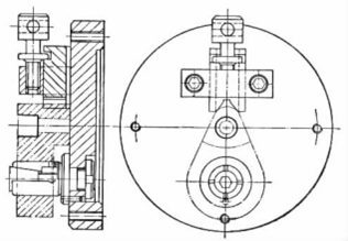
Figure 6-1-27 Lever part turning lathe fixture
2. Key points of lathe fixture design
(1) Design of connecting elements.
The configuration of connecting elements in lathes and cylindrical grinders primarily depends on the spindle end structure of the machine tool. As these two types of fixtures share similar connection methods with their respective machine tools, this discussion will focus on lathes as a representative example. Common connection configurations include the following types:
① The fixture connects to the machine tool spindle's front center and the tailstock's rear center through front and rear center holes, driven by a dial. This connection method is commonly used for longer locating spindles.
② The fixture connects to the machine tool spindle's Morse taper hole via a Morse taper shank. When required, a long screw rod can be inserted through the spindle hole from the rear to tighten the fixture, thereby increasing the friction torque on the contact surface. This connection method ensures excellent centering accuracy and enables quick, convenient installation and removal. However, it has lower rigidity and is suitable for short locating spindles and small fixtures.
③ The fixture is directly connected to the end of the lathe spindle, as shown in Figure 6-1-28. In Figure 6-1-28(a), the fixture body connects to the lathe spindle's short conical body and end face T through short conical hole K and end face T, secured with screws. This connection method ensures high centering accuracy and rigidity. However, during manufacturing, it requires not only maintaining the conical taper and strictly controlling the diameter of the conical hole, but also ensuring the perpendicularity between the conical hole and end face to achieve optimal contact between the conical body and end face. Consequently, the fixture body becomes more complex to manufacture, making it particularly challenging to achieve interchangeability with spindle ends of various lathe models. Nevertheless, this spindle end structure is the standard form specified by national regulations, leading to its increasingly widespread application. In Figure 6-1-28(b), the fixture body connects to the lathe spindle's shaft neck and end face through end face T and cylindrical hole D, secured with M threads and two safety blocks 2 to prevent reverse rotation.
When rotating, the threaded connection becomes loose. This connection method simplifies part manufacturing, but the cylindrical mating creates clearance and results in lower centering accuracy. This approach is commonly used for connecting fixtures to the ends of lathes such as C620, C620-1, and C630. Figure 6-1-28(c) shows the fixture body connected to the spindle cone via a 1:4 taper hole, with the fixture tightened by the spindle's tension nut 3 and torque transmitted through key 4. Due to the lack of end face connection, this method has poor rigidity and is typically used for lightweight fixtures. The same connection method applies to fixtures mounted on spindle ends of lathes like C616.
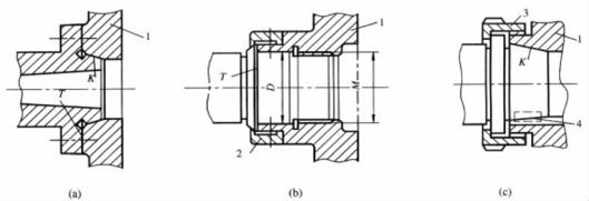
Figure 6-1-28 Direct connection of fixture to end of lathe spindle
1-Clamping body 2-Safety block 3-Tension nut 4-Key
④ The fixture is connected to the lathe spindle end through a transition disc, as shown in Figure 6-1-29. The connection between the transition disc 2 and the lathe spindle end can vary depending on the spindle end structure, as illustrated in Figure 6-1-29. For example, Figure 6-1
-29(a) The transition disc connects to the machine tool spindle's short conical end face via a short conical hole and end face. The other end of the transition disc is attached to the fixture. This connection method not only enables the fixture to adapt to various spindle end configurations of machine tools, but also
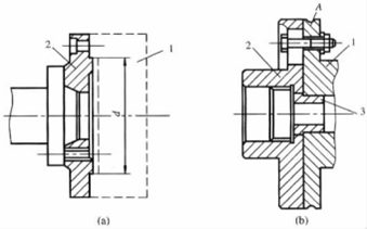
Figure 6-1-29 Connection with transition disc
1-Jig 2-Transition Plate 3-Installation Sleeve A-Alignment Base
This design enables machine tools to accommodate various fixtures, significantly enhancing versatility. As shown in Figure 6-1-29(a), transition discs are typically connected to fixtures using end face and cylindrical surface joints, with diameters d generally fitted with K7/h6 or M7/h6 clearance fits. However, the intermediate transition disc may compromise fixture centering accuracy. To improve this, the alignment base surface connection method illustrated in Figure 6-1-29(b) can be employed. In this configuration, fixture A is first pre-tensioned onto transition disc 2. Alignment is performed using a dial indicator to align with base surface A, followed by adjusting the fixture's rotational axis to coaxiality with the machine tool spindle. The installation sleeve 3 serves as a predetermined centering element, facilitating alignment through a substantial clearance fit with the transition disc.
This ensures the need for adjusting the fixture during alignment. The installation sleeve can also serve as a support for the fixture before alignment. To protect the alignment base surface from damage, the A surface should be made into a groove.
Some lathes that do not use the transition disc stop connection method, and can not directly align the fixture rotation axis with the positioning element, must also design the alignment base (external ring surface or internal hole) to align the fixture rotation axis with the machine tool spindle rotation axis.
(2) Other design points of lathe fixtures.
In addition to the important design of connecting elements, the following issues should be considered when designing lathes and grinding machine fixtures:
① When designing chuck and flower plate lathe fixtures, the external dimensions should be as compact as possible, and the center of gravity should coincide with the rotation axis to reduce the influence of centrifugal force and rotation torque.
② Shorten the hanging length of the fixture, so that the center of gravity is close to the spindle, so as to reduce the bending load of the spindle and ensure the machining accuracy.
③ When the center of gravity of the fixture (including the workpiece) deviates from the machine tool's spindle axis, particularly if the fixture structure is asymmetrical relative to the rotation axis, balancing measures must be implemented. This may involve adding balance weights with arc-shaped (or radial) slots for easy position adjustment. For high-speed rotating fixtures, specialized dynamic balancing tests should be conducted to ensure operational safety and machining quality.
④ The combined outer diameter of the fixture and workpiece during rotation must not exceed the machine's permissible rotation limit. The fixture components and the workpiece mounted on them should not extend beyond the fixture body. Additionally, the rotating parts should be designed with smooth surfaces to eliminate sharp edges, and protective enclosures should be installed.
⑤ For high-speed rotating fixtures, special attention should be paid to secure clamping to prevent the danger of workpiece flying out.
⑥ The structure of the grinding machine fixture is similar to that of the lathe fixture, but the processing technology of the grinding machine requires higher precision, so the manufacturing precision and rotary balance of the fixture should have higher requirement.
Conclusion
The right equipment is key for outer cylindrical surfaces. A lathe, suitable cutting tools, precise grinding wheels, and stable fixtures are all essential for achieving quality, precision, and efficiency.