Everything You Need to Know about Pipe Thread

Confused by pipe thread types? Choosing the wrong one causes leaks, project delays, and costly rework. Understanding the key differences saves you time, money, and a massive headache.
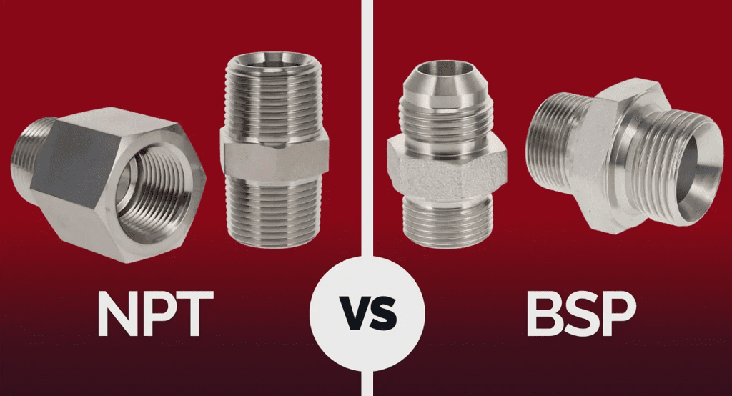
The most important thing to know about pipe threads is that they are not all the same. The two major standards are the British Standard Pipe (BSP) with a 55° thread angle and the American National Pipe Thread (NPT) with a 60° thread angle. They are not interchangeable.
When I first started in this business, I remember a client, let's call him Mark, who was sourcing parts from multiple suppliers for a big project. He accidentally ordered fittings with NPT threads from one vendor and pipes with BSP threads from another. It was a complete disaster. Nothing fit. The project was delayed by weeks, and the cost of replacing the wrong parts was huge. This experience taught me a valuable lesson: details like thread type are not small details; they are critical. Getting them right from the start is everything. So, let's break down these thread types to make sure this never happens to you
一 Threaded pipe with thread seal (55. Tooth angle)
The GB/T 7306—1987 standard for threaded pipe connections specifies two types: conical internal and external threads, and cylindrical internal and external threads. Both connection methods ensure sealing performance, and sealing packing may be added to the threaded pair when necessary.
(一) Tooth type and element name code
(1) Basic thread profile of conical thread (see Figure 4-1-12)
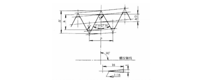
Figure 4-1-12 Basic thread profile of conical thread
(2)Basic thread profile of cylindrical thread (see Figure 4-1-13)

Figure 4-1-13 Basic thread profile of cylindrical internal thread
(3) Factor name and code (see Table 4-1-37)
Table 4-1-37 Element Name and Code
| name | code name |
| Large diameter internal thread | D |
| Large diameter external thread | d |
| Internal thread diameter | D2 |
| External thread diameter | d2 |
| Internal thread diameter | D1 |
| External thread diameter | d1 |
| pitch | P |
| Original triangle height | H |
| Tooth height | h |
| Arc radius | r |
| Number of threads per 25.4mm | n |
| Base distance tolerance | T1 |
| Axial displacement tolerance of the conical internal thread reference plane | T2 |
(二) Basic dimensions of thread
The size of the conical pipe thread is given on the reference plane, and the size of the cylindrical internal thread that mates with the conical external thread is the same as the size of the conical internal thread on the reference plane of the same specification.
The values of the pitch diameter and pitch diameter are calculated by the following formula:
d2 = D2 = d-0.640327p
d1 = D1 = d-1.280654p
Table 4-1-38 Thread Basic Dimensions (mm)
Thread size code | every25 .4mmNumber of teethn | pitch P | dental patternaltitudeh | Arc radius r ≈ | Basic diameter on the base | Baseline distance | Effective thread length | ||
| Large Diameter( datum diameter )d = D | Middle diameter d2 = D2 | Path d1 = D1 | |||||||
| 1/16 | 28 | 0 .907 | 0 .581 | 0 . 125 | 7 .723 | 7 . 142 | 6 .561 | 4 .0 | 6 .5 |
| 1/8 | 28 | 0 .907 | 0 .581 | 0 . 125 | 9 .728 | 9 . 147 | 8 .566 | 4 .0 | 6 .5 |
| 1/4 | 19 | 1 . 337 | 0 . 856 | 0 . 184 | 13 . 157 | 12 . 301 | 11 .445 | 6 .0 | 9 .7 |
| 3/8 | 19 | 1 . 337 | 0 . 856 | 0 . 184 | 16 . 662 | 15 . 806 | 14 .950 | 6 .4 | 10 . 1 |
| 1/2 | 14 | 1 . 814 | 1 . 162 | 0 .249 | 20 .955 | 19 .793 | 18 . 631 | 8 .2 | 13 .2 |
| 3/4 | 14 | 1 . 814 | 1 . 162 | 0 .249 | 26 .441 | 25 .279 | 24 . 117 | 9 .5 | 14 .5 |
| 1 | 11 | 2 . 309 | 1 .479 | 0 . 317 | 33 .249 | 31 .770 | 30 .291 | 10 .4 | 16 . 8 |
| 1!4 | 11 | 2 . 309 | 1 .479 | 0 . 317 | 41 .910 | 40 .431 | 38 .952 | 12 .7 | 19 . 1 |
| 1!2 | 11 | 2 . 309 | 1 .479 | 0 . 317 | 47 . 803 | 46 . 324 | 44 . 845 | 12 .7 | 19 . 1 |
| 2 | 11 | 2 . 309 | 1 .479 | 0 . 317 | 59 . 614 | 58 . 135 | 56 . 656 | 15 .9 | 23 .4 |
| 2Y2 | 11 | 2 . 309 | 1 .479 | 0 . 317 | 75 . 184 | 73 .705 | 72 .226 | 17 .5 | 26 .7 |
| 3 | 11 | 2 . 309 | 1 .479 | 0 . 317 | 87 . 884 | 86 .405 | 84 .926 | 20 .6 | 29 . 8 |
| 3Y2① | 11 | 2 . 309 | 1 .479 | 0 . 317 | 100 . 330 | 98 . 851 | 97 . 372 | 22 .2 | 31 .4 |
| 4 | 11 | 2 . 309 | 1 .479 | 0 . 317 | 113 .030 | 111 .551 | 110 .072 | 25 .4 | 35 . 8 |
| 5 | 11 | 2 . 309 | 1 .479 | 0 . 317 | 138 .430 | 136 .951 | 135 .472 | 28 . 6 | 40 . 1 |
| 6 | 11 | 2 . 309 | 1 .479 | 0 . 317 | 163 . 830 | 162 . 351 | 160 . 872 | 28 . 6 | 40 . 1 |
What is the Thread tolerance?
Since tapered threads have a 1:16 taper along the axial direction, when the major diameter of the thread at a specified axial position deviates, the plane at that position ceases to serve as the reference plane. Instead, the plane at another position where the major diameter equals the reference diameter becomes the new reference plane. The distance between these two planes represents the displacement of the reference plane. Therefore, specifying the axial displacement tolerance of the reference plane is equivalent to defining the tolerance for the tapered thread diameter.
The tolerance and limit deviation of the cylindrical internal thread mating with the conical external thread are the same as those of the conical internal thread. The limit deviation for each diameter is 1/16 of the axial displacement of the base surface of the same specification conical internal thread.
Table 4-1-39 Thread Tolerances
Thread size code | Every 25.4 mm the number of teeth n | Baseline distance (mm) | Conical internal thread base surfaceLimit of axial displacement bias /mm | fitting allowance /mm≈ | Effective thread length/mm not less than ① | ||||||||
basic | Tolerance | maximum | minimum | ||||||||||
| ±T1/2≈ | number of turns | ||||||||||||
| ± T2/2≈ | number of turns | allowance | number of turns | basic | maximum | minimum | |||||||
| 1/16 | 28 | 4 .0 | 0 .9 | 1 | 4 .9 | 3 . 1 | 1 . 1 | 1Y4 | 2 .5 | 2Y4 | 6 .5 | 7 .4 | 5 . 6 |
| 1/8 | 28 | 4 .0 | 0 .9 | 1 | 4 .9 | 3 . 1 | 1 . 1 | 1Y4 | 2 .5 | 2Y4 | 6 .5 | 7 .4 | 5 . 6 |
| 1/4 | 19 | 6 .0 | 1 . 3 | 1 | 7 . 3 | 4 .7 | 1 .7 | 1Y4 | 3 .7 | 2Y4 | 9 .7 | 11 .0 | 8 .4 |
| 3/8 | 19 | 6 .4 | 1 . 3 | 1 | 7 .7 | 5 . 1 | 1 .7 | 1Y4 | 3 .7 | 2Y4 | 10 . 1 | 11 .4 | 8 . 8 |
| 1/2 | 14 | 8 .2 | 1 . 8 | 1 | 10 .0 | 6 .4 | 2 . 3 | 1Y4 | 5 .0 | 2Y4 | 13 .2 | 15 .0 | 11 .4 |
| 3/4 | 14 | 9 .5 | 1 . 8 | 1 | 11 . 3 | 7 .7 | 2 . 3 | 1Y4 | 5 .0 | 2Y4 | 14 .5 | 16 . 3 | 12 .7 |
| 1 | 11 | 10.4 | 2.3 | 1 | 12.7 | 8 . 1 | 2.9 | 1Y4 | 6.4 | 2Y4 | 16.8 | 19 . 1 | 14.5 |
| 1Y4 | 11 | 12.7 | 2.3 | 1 | 15.0 | 10.4 | 2.9 | 1Y4 | 6.4 | 2Y4 | 19 . 1 | 21.4 | 16.8 |
| 1Y2 | 11 | 12.7 | 2.3 | 1 | 15.0 | 10.4 | 2.9 | 1Y4 | 6.4 | 2Y4 | 19 . 1 | 21.4 | 16.8 |
| 2 | 11 | 15.9 | 2.3 | 1 | 18.2 | 13.6 | 2.9 | 1Y4 | 7.5 | 3Y4 | 23.4 | 25.7 | 21 . 1 |
| 2Y2 | 11 | 17.5 | 3 .5 | 1Y2 | 21.0 | 14.0 | 3 .5 | 1Y2 | 9.2 | 4 | 26.7 | 30.2 | 23.2 |
| 3 | 11 | 20.6 | 3 .5 | 1Y2 | 24. 1 | 17 . 1 | 3 .5 | 1Y2 | 9.2 | 4 | 29.8 | 33.3 | 26.3 |
| 3Y2① | 11 | 22.2 | 3 .5 | 1Y2 | 25.7 | 18.7 | 3 .5 | 1Y2 | 9.2 | 4 | 31.4 | 34.9 | 27.9 |
| 4 | 11 | 25.4 | 3 .5 | 1Y2 | 28.9 | 21.9 | 3 .5 | 1Y2 | 10.4 | 4Y2 | 35.8 | 39.3 | 32.3 |
| 5 | 11 | 28.6 | 3 .5 | 1Y2 | 32. 1 | 25. 1 | 3 .5 | 1Y2 | 11 .5 | 5 | 40. 1 | 43.6 | 36.6 |
| 6 | 11 | 28.6 | 3 .5 | 1Y2 | 32. 1 | 25. 1 | 3 .5 | 1Y2 | 11 .5 | 5 | 40. 1 | 43.6 | 36.6 |
① Minimum effective thread length for internal and external threads = Base distance + assembly allowance. The values in the "Effective Thread Length" column of the table represent minimum effective thread lengths specified relative to three base distances. To accommodate external threads, when the internal thread's effective thread length is less than the maximum value, the internal thread's effective thread length must not be shorter than that of the external thread.
② Thread size code 3Y2 is limited to steam locomotives.
The relationship between the reference plane of the internal and external conical threads and the effective thread length is shown in Figure 4-1-14. Figure C shows the thread without tail, and the effective thread length should not be less than 80% of the minimum effective thread length in Table 4-1-39.
Thread code and marking examples
The letter Rc denotes a conical internal thread, R indicates a conical external thread, and Rp represents a cylindrical internal thread that mates with the cone.
Example marker:
Cone internal thread Rc1Y2;
Cylindrical internal thread with taper Rp 1Y2;
Cone external thread R1Y2.
When the thread is left-hand, add 'LH' after the size code, e.g. R12-LH
When the internal and external threads are assembled together, the internal and external threads are separated by a diagonal line, the left side represents the internal thread, the right side represents the external thread.
Example marker:
Thread fit between the conical internal and external
threads: Rcl2/R12.
The internal thread of the cylindrical part matching the conical part
and the external thread of the conical part: Rp 1 2/R1 2;
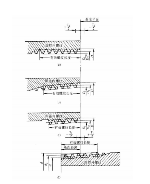
Figure 4-1-14: Position of the reference plane and effective thread length
Thread fit between left-hand conical internal and conical
external threads: Rc1 2 R1 2-LH
二. Non-threaded pipe threads (55° chamfered angle)
The pipe thread standard (GB/T 7307-1987) specifies that both internal and external threads are cylindrical, lacking sealing capability (used solely for mechanical connection). For sealing performance after connection, additional sealing methods may be applied externally to the thread pair.
(一) Tooth profile and tooth profile dimension calculation (see Figure 4-1-15)

Figure 4-1-15 Basic thread profile of cylindrical pipe thread
P H = 0 . 960491P
h = 0 . 640327P r = 0 . 137329P
P
n — Number of threads per 25.4mm
The distribution of tolerance bands is shown in Figure 4-1-16.
(二) Basic dimensions and tolerances
The basic dimensions of the thread's mean and minor diameters are calculated using the following formulas:
d2 = D2 = d - 0 . 640327p
d 1 = D1 = d - 1 . 280645p
The internal thread's medium diameter has a single tolerance with zero lower deviation and a positive upper deviation. The external thread's medium diameter tolerance is divided into two grades, A and B, both with zero upper deviation and negative lower deviation. The thread's crest may be flattened within the specified tolerance range.
The basic dimensions and tolerances of cylindrical pipe threads are shown in Table 4-1-40
(三) Thread code and marking examples
The marking of cylindrical pipe thread consists of thread characteristic code, size code, and tolerance grade code. The thread characteristic code is represented by the letter G.
Example of a marker:
External thread Grade A G1 2A;
External thread Grade B G1 2 B;
Internal thread G1 2. Internal thread G1 2.
When the thread is left-hand, add 'LH' after the tolerance grade code. For example
, G1 2 — LH; G1 2A — LH.
When assembling internal and external threads, the markings are separated by a slash, with the left side indicating the internal thread
and
the
right side the external thread. For example, G1 2/G1 2A; G1 2/ G1 2 B.

Figure 4-1-16 Thread tolerance band
Table 4-1-40 Basic Dimensions and Tolerances of Threads
Thread size code | Every 2.54mm innernumber of teethn | pitch P | Toothaltitudeh | Arc radius r ≈ Arc radius r ≈ | basic size | external screw thread | internal thread | |||||||||
Large diameter d = D | Middle diameter d2 =D2 | Path d1 =D1 | Large diameter tolerance Td | Middle diameter tolerance Td | Middle diameter tolerance TD | Small path tolerance TD1 | ||||||||||
| lower deviation | upper deviation | lower deviation | upper deviation | lower deviation | upper deviation | lower deviation | upper deviation | |||||||||
| A level | B level | |||||||||||||||
| 1/161/81/43/8 1/25/83/47/8 11 8 1 4 2 4 4 2 | 28281919 14141414 11111111 11111111 11111111 11111111 | 0 .9070 .9071 . 3371 . 337 1 . 8141 . 8141 . 8141 . 814 2 . 3092 . 3092 . 3092 . 309 2 . 3092 . 3092 . 3092 . 309 2 . 3092 . 3092 . 3092 . 309 2 . 3092 . 3092 . 3092 . 309 | 0 .5810 .5810 . 8560 . 856 1 . 1621 . 1621 . 1621 . 162 1 .4791 .4791 .4791 .479 1 .4791 .4791 .4791 .479 1 .4791 .4791 .4791 .479 1 .4791 .4791 .4791 .479 | 0 . 1250 . 1250 . 1840 . 184 0 .2490 .24902490249 0 . 3170 . 3170 . 3170 . 317 0 . 3170 . 3170 . 3170 . 317 0 . 3170 . 3170 . 3170 . 317 0 . 3170 . 3170 . 3170 . 317 | 7 .7239 .72813 . 15716 .662 20 .95522 .91126 .44130 .201 33 .24937 . 89741 .91047 . 803 53 .74659 .61465 .71075 . 184 81 .53487 . 884100.330113.030 125.730138.430151.130163.830 | 7 . 1429 . 14712 . 30115 . 806 19 .79321 .74925 .27929 .039 31 .77036 .41840 .43146 . 324 52 .26758 . 13564 .23173 .705 80 .05586 .40598 . 851111.551 124.251136.951149.651162.351 | 6 .5618 .56611 .44514 .950 18 .63120 .58724 . 11727 . 877 30 .29134 .93938 .95244 . 845 50 .78856 .65662 .75272 .226 78 .57684 .92697 . 372110.072 122.772135.472148.172160.872 | - 0.214- 0.214- 0.250- 0.250 - 0.284- 0.284- 0.284- 0.284 - 0.360- 0.360- 0.360- 0.360 - 0.360- 0.360- 0.434- 0.434 - 0.434- 0434- 0.434- 0.434 - 0.434- 0434- 0.434- 0.434 | 0000 0000 0000 0000 0000 0000 | - 0.107- 0.107- 0.125- 0.125 - 0.142- 0.142- 0.142- 0.142 - 0.180- 0.180- 0180- 0.180 - 0.180- 0.180- 0.217- 0.217 - 0.217- 0.217- 0.217- 0.217 - 0.217- 0.217- 0.217- 0.217 | - 0.214- 0.214- 0.250- 0.250 - 0.284- 0.284- 0.284- 0.284 - 0.360- 0.360- 0.360- 0.360 - 0.360- 0.360- 0.434- 0.434 - 0.434- 0.434- 0.434- 0.434 - 0.434- 0.434- 0.434- 0.434 | 0000 0000 0000 0000 0000 0000 | 0000 0000 0000 0000 0000 0000 | + 0 . 107+ 0 . 107+ 0 . 125+ 0 . 125 + 0 . 142+ 0 . 142+ 0 . 142+ 0 . 142 + 0 . 180+ 0 . 180+ 0 . 180+ 0 . 180 + 0 . 180+ 0 . 180+ 0 .217+ 0 .217 + 0 .217+ 0 .217+ 0 .217+ 0 .217 + 0 .217+ 0.217+ 0 .217+ 0.217 | 0000 0000 0000 0000 0000 0000 | + 0.282+ 0.282+ 0.445+ 0.445 + 0.541+ 0.541+ 0.541+ 0.541 + 0.640+ 0.640+ 0.640+ 0.640 + 0.640+ 0.640+ 0.640+ 0.640 + 0.640+ 0.640+ 0.640+ 0.640 + 0.640+ 0.640+ 0.640+ 0.640 |
| CO2 | 0 . 1% | CnHn | ≤0 . 2% |
| O2 | 0 . 2% ~ 0 . 8% | CO | 10% ~ 15% |
| H2 | 50% ~ 70% | CnH2n+ 2 | 10% ~ 15% |
60° Tapered pipe thread
The 60° tapered pipe thread has performance comparable to the 55° angle pipe thread. To ensure the sealing of the thread pair, sealing packing can be added.
(一) Thread terms and codes
Table 4-1-41 Thread terms and codes
| term | code name |
| Large diameter internal thread | D |
| Large diameter external thread | d |
| Internal thread diameter | D2 |
| External thread diameter | d2 |
| Internal thread diameter | D1 |
| External thread diameter | d1 |
| pitch | P |
| Original triangle height | H |
| Tooth height | h |
| Number of teeth per 25.4mm | n |
| Smooth height | 『 |
| datum diameter | - |
| base plane | - |
| Baseline distance | L1 |
| Full thread length | L5 |
| Incomplete thread length | L6 |
| Tail length | V |
| Effective thread length | L2 |
| fitting allowance | L3 |
| Tightening allowance | L4 |
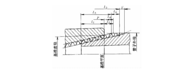
(二) Thread profile and dimensions
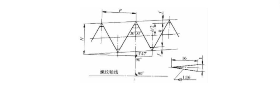
Figure 4-1-17 Basic thread profile of 60° tapered pipe thread
(三) Basic dimensions of 60 °conical pipe thread
(1) Basic dimensions of 60° tapered pipe threads (see Table 4-1-42)
Table 4-1-42 Basic Dimensions of 60° Conical Pipe Thread (mm)
Thread size code | Every 25.4mmThreadedNumber of teeth n | Basic diameter on the base | Baseline distance | fitting allowance | ||||
| Large diameter (base diameter) d = D | Middle diameter d2 = D2 | Path d1 = D1 | ||||||
| L1 | Number of teeth | L3 | Number of teeth | |||||
| 1/16 | 27 | 7 . 895 | 7 . 142 | 6 . 389 | 4 .064 | 4 . 32 | 2 . 822 | 3 |
| 1/8 | 27 | 10 .242 | 9 .489 | 8 .736 | 4 . 102 | 4 . 36 | 2 . 822 | 3 |
| 1/4 | 18 | 13 . 616 | 12 .487 | 11 . 358 | 5 .786 | 4 . 10 | 4 .234 | 3 |
| 3/8 | 18 | 17 .055 | 15 .926 | 14 .797 | 6 .096 | 4 . 32 | 4 .234 | 3 |
| 1/2 | 14 | 21 .223 | 19 .772 | 18 . 321 | 8 . 128 | 4 .48 | 5 .443 | 3 |
| 3/4 | 14 | 26 .568 | 25 . 117 | 23 . 666 | 8 . 611 | 4 .75 | 5 .443 | 3 |
| 1 | 11 .5 | 33 .228 | 31 .461 | 29 . 694 | 10 . 160 | 4 . 60 | 6 . 627 | 3 |
| 1 4 | 11 .5 | 41 .985 | 40 .218 | 38 .451 | 10 . 668 | 4 . 83 | 6 . 627 | 3 |
| 1 2 | 11 .5 | 48 .054 | 46 .287 | 44 .520 | 10 . 668 | 4 . 83 | 6 . 627 | 3 |
| 2 | 11 .5 | 60 .092 | 58 . 325 | 56 .558 | 11 .074 | 5 .01 | 6 . 627 | 3 |
| 2 2 | 8 | 72 . 699 | 70 . 159 | 67 . 619 | 17 . 323 | 5 .46 | 6 . 350 | 2 |
| 3 | 8 | 88 . 608 | 86 .068 | 83 .528 | 19 .456 | 6 . 13 | 6 . 350 | 2 |
| 3 2 | 8 | 101 . 316 | 98 .776 | 96 .236 | 20 . 853 | 6 .57 | 6 . 350 | 2 |
| 4 | 8 | 113 .973 | 111 .433 | 108 . 893 | 21 .438 | 6 .75 | 6 . 350 | 2 |
| 5 | 8 | 140 .952 | 138 .412 | 135 . 872 | 23 . 800 | 7 .50 | 6 . 350 | 2 |
| 6 | 8 | 167 .792 | 165 .252 | 162 .712 | 24 . 333 | 7 . 66 | 6 . 350 | 2 |
| 8 | 8 | 218 .441 | 215 .901 | 213 . 361 | 27 .000 | 8 .50 | 6 . 350 | 2 |
| 10 | 8 | 272 . 312 | 269 .772 | 267 .232 | 30 .734 | 9 . 68 | 6 . 350 | 2 |
| 12 | 8 | 323 .032 | 320 .492 | 317 .952 | 34 .544 | 10 . 88 | 6 . 350 | 2 |
(2) Basic dimensions of tapered pipe threads (inches) (see Table 4-1-43)
Table 4-1-43 Basic dimensions of tapered pipe threads (inches)
Thread size code | per inchThread countn | Basic diameter on the base | Baseline distance | fitting allowance | ||||
| Large diameter (base diameter)d = D/in | pitch diameterd2 = D2/in | pathwayd1 = D1/in | ||||||
| L1/in | Number of teeth | L3/in | Number of teeth | |||||
| 1/16 | 27 | 0 . 31081 | 0 .28118 | 0 .25155 | 0 . 160 | 4 . 32 | 0 . 1111 | 3 |
| 1/8 | 27 | 0 .40323 | 0 . 37360 | 0 . 34397 | 0 . 1615 | 4 . 36 | 0 . 1111 | 3 |
| 1/4 | 18 | 0 .53607 | 0 .49163 | 0 .44719 | 0 .2278 | 4 . 10 | 0 . 1667 | 3 |
| 3/8 | 18 | 0 . 67145 | 0 . 62701 | 0 .58257 | 0 .240 | 4 . 32 | 0 . 1667 | 3 |
| 1/2 | 14 | 0 . 83557 | 0 .77843 | 0 .72129 | 0 . 320 | 4 .48 | 02143 | 3 |
| 3/4 | 14 | 1 .04601 | 0 .98887 | 0 .93173 | 0 . 339 | 4 .75 | 0 .2143 | 3 |
| 1 | 11 .5 | 1 . 30820 | 1 .23863 | 1 . 16906 | 0 .400 | 4 . 60 | 0 .2609 | 3 |
| 1 4 | 11 .5 | 1 . 65295 | 1 .58338 | 1 .51381 | 0 .420 | 4 . 83 | 0 .2609 | 3 |
| 1 2 | 11 .5 | 1 . 89191 | 1 . 82234 | 1 .75277 | 0 .420 | 4 . 83 | 0 .2609 | 3 |
| 2 | 11 .5 | 2 . 36584 | 229627 | 2 .22670 | 0 .436 | 5 .01 | 0 .2609 | 3 |
| 2 2 | 8 | 2 . 86216 | 2 .76216 | 2 . 66216 | 0 . 682 | 5 .46 | 02500 | 2 |
| 3 | 8 | 3 .48850 | 3 . 38850 | 3 .28850 | 0 .766 | 6 . 13 | 0 .2500 | 2 |
| 3 2 | 8 | 3 .98881 | 3 . 88881 | 3 .78881 | 0 . 821 | 6 .57 | 0 .2500 | 2 |
| 4 | 8 | 4 .48712 | 4 . 38712 | 4 .28712 | 0 . 844 | 6 .75 | 0 .2500 | 2 |
| 5 | 8 | 5 .54929 | 5 .44929 | 5 . 34929 | 0 .937 | 7 .50 | 0 .2500 | 2 |
| 6 | 8 | 6 . 60597 | 6 .50597 | 6 .40597 | 0 .958 | 7 . 66 | 0 .2500 | 2 |
| 8 | 8 | 8 . 60003 | 8 .50003 | 8 .40003 | 1 .063 | 8 .50 | 0 .2500 | 2 |
| 10 | 8 | 10 .72094 | 10 . 62094 | 10 .52094 | 1 .210 | 9 . 68 | 0 .2500 | 2 |
| 12 | 8 | 12 .71781 | 12 . 61781 | 12 .51781 | 1 . 360 | 10 . 88 | 0 .2500 | 2 |
(四) 60 °Cone pipe thread tolerance
1) Both the maximum permissible deviation of the conical external thread's reference distance and the maximum permissible deviation of the conical internal thread's axial position are ±P.
2) The tolerance of the crest height and root height of the conical pipe thread is shown in Table 4-1-44.
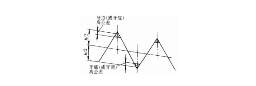
3) The fillet of the thread crest may extend beyond the crest tolerance zone, provided its apex remains within the zone; similarly, the fillet of the thread root must not extend beyond the root tolerance zone (see Figure 4-1-18).
4) Maximum permissible deviations for thread profile half-angle, taper half-angle, and pitch (see Table 4-1-45)
Table 4-1 (pages 44-60): Tolerances for the crest height and root height of conical pipe threads
| Number of threads per 25.4mm | Top and bottom tooth heights tolerance (mm) |
| 27 | 0 .059 |
| 18 | 0 .078 |
| 14 | 0 .081 |
| 11 .5 | 0 .088 |
| 8 | 0 .092 |
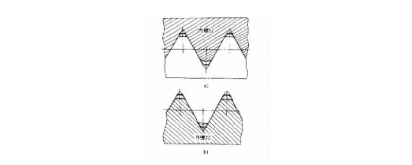
Figure 4-1-18 chamfering of the inner and outer thread tooth tips and bases
Table 4-1-45: Limit deviations of thread profile half-angle, taper half-angle, and pitch
| Every 25.4mmNumber of internal threads n | Tooth angle half-angle deviation | Midline cone half-angle deviation | screw-pitch deviation /mm | ||
| external screw thread | internal thread | l ≤ 10 | l > 10 | ||
| 27181411 .58 | ± 1o | + 12’— 6’ | + 6’— 12’ | ± 0 .02 | ± 0 .04 |
± 45’ | + 10’— 5’ | + 5’— 10’ | |||
(五) Thread code and marking examples
The 60° tapered pipe thread marking consists of the symbol "NPT" and the thread size code. When the thread is left-hand, "LH" is added after the size code.
Example label: NPT3/8 — LH
四. What is Rice conical thread?
The metric tapered thread consists of two types: conical internal thread and conical external thread, as well as cylindrical internal thread and conical external thread. To improve sealing, sealing filler is allowed to be added to the thread mating surface.
(一) Thread type
The original triangular profile of the American taper thread is a 60° equilateral triangle. The chamfer heights for the major and minor diameters are H/8 and H/4 respectively, with a taper ratio of 1:16. The angle bisector of the thread tooth is perpendicular to the thread axis (see Figure 4-1-19).
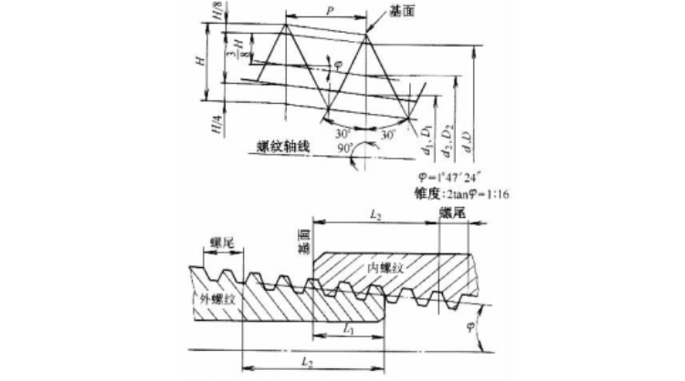
Figure 4-1-19 Metric tapered thread thread form
(二) Basic dimensions
The basic dimensions of large, medium and small diameter of American taper thread are given on the basic plane, and the basic dimensions also include the reference distance and effective thread length.
The internal thread of the cylindrical part that mates with the external conical thread shall have the same thread profile and dimensions as the standard thread (the thread profile and dimensions shall comply with the provisions of GB/T 192, GB/T 193, and GB/T 196). The effective thread length shall not be less than 80% of the corresponding specification's effective thread length L2 for the conical thread.
The basic dimensions of American taper thread are shown in Table 4-1-46.
Table 4-1-46 Basic dimensions of metric tapered threads
| Thread sizeDiameterd、D | pitch P | Thread diameter on the base | Base distance L1 | Effective thread length L2 | ||||
| Large diameter d = D | Middle diameter d2 = D2 | Path d1 = D1 | Standard base distance | Short interval | Effective thread length of standard | Short effective thread length | ||
| 6810 | 1 | 6 .0008 .00010 .000 | 5 . 3507 . 3509 . 350 | 4 .9176 .9178 .917 | 5 .5 | 2 .5 | 8 | 5 |
| 12141618202224 | 1 .5 | 12 .00014 .00016 .0018 .00020 .00022 .00024 .000 | 11 .02613 .02615 .02617 .02619 .02621 .02623 .026 | 10 . 37612 . 37614 . 37616 . 37618 . 37620 . 37622 . 376 | 7 .5 | 3 .5 | 11 | 7 |
| 2730333639424548525660 | 2 | 27 .00030 .00033 .00036 .00039 .00042 .00045 .00048 .00052 .00056 .00060 .000 | 25 .70128 .70131 .70134 .70137 .70140 .70143 .70146 .70150 .70154 .70158 .701 | 24 . 83527 . 83530 . 83533 . 83536 . 83539 . 83542 . 83545 . 83549 . 83553 . 83557 . 835 | 11 | 5 | 16 | 10 |
(三) Metric taper thread tolerance
(1) Limit deviations of the bearing distance and axial displacement of the bearing surface (see Table 4-1-47)
Table 4-1-47 Maximum allowable deviations of the base distance and axial displacement of the base surface (mm)
| Thread nominal diameter d, D | pitch P | The limit deviation of the external thread reference distance( ± T2/2) | The axial displacement of the internal thread base surfaceLimit deviation (± T2/2) |
| 6 ~ 10 | 1 | ± 0 . 9 | ± 1 . 2 |
| > 10 ~ 24 | 1.5 | ± 1 . 1 | ± 1 . 5 |
| > 24 ~ 60 | 2 | ± 1 .4 | ± 1 . 8 |
(2) Maximum deviations for major and minor thread diameters (see Table 4-1-48)
Table 4-1-48 Maximum Tolerances for Major and Minor Thread Diameter (mm)
| Thread nominal diameterd,D | P | External thread tolerance | Internal thread limit deviation | ||
| Large Diameter | pathway | Large Diameter | pathway | ||
6 ~ 10 | 1 | 0— 0 .064 | + 0 . 100+ 0 . 030 | ± 0 . 060 | ± 0 . 060 |
> 10 ~ 24 | 1 .5 | 0— 0 . 096 | + 0 . 130+ 0 .040 | ± 0 . 080 | ± 0 . 080 |
> 24 ~ 60 | 2 | 0— 0 . 128 | + 0 . 170+ 0 . 060 | ± 0 . 100 | ± 0 . 100 |
(3)Large diameter tolerance for cylindrical internal threads (see Table 4-1-49)
Table 4-1: Large Diameter Tolerance for Internal Cylindrical Thread (mm)
| Thread nominal diameter D | pitch P | Thread major diameter limit deviation |
| 6 ~ 10 | 1 | ± 0 .045 |
| > 10 ~ 24 | 1 .5 | ± 0 .065 |
| > 24 ~ 60 | 2 | ± 0 .085 |
(4) Other thread tolerance elements (see Table 4-1-50)
Table 4-1: Tolerances for Other Elements of Thread 50 (mm)
| Nominal thread diameter d, D | pitch P | A/2 limit deviation for half-angle tooth profile | Thread pitch P limit deviation | Inclination angle φ Limit deviation | ||
| L1 | L2 | external screw thread | internal thread | |||
| 6 ~ 10> 10 ~ 24> 24 ~ 60 | 11.52 | ± 45/ | ± 0 .04 | ± 0 .07 | + 12/— 6/ | + 6/— 12/ |
(5) Thread code and marking examples
A metric tapered thread is denoted by the letter "ZM" followed by its nominal outer diameter on the root face. For example, ZM10 indicates a metric tapered thread with a root face diameter of 10mm and a pitch of 1mm.
Conclusion
Understanding pipe threads is vital. The main types, BSP (55°) and NPT (60°), are not interchangeable. Choosing the correct standard is critical for preventing leaks and ensuring project success.