How does Cutting Force and Cutting Power Affect Machining Process?

Ever wondered what truly dictates the final quality and cost of your CNC machined parts? Beyond the obvious factors, an invisible force is at play: cutting force. Understanding and controlling this, along with cutting power, is the secret to achieving precision, efficiency, and optimal results. This guide breaks down these critical concepts, empowering you to make smarter design and manufacturing choices.
What is Cutting Force?
During machining, the tool induces elastic and plastic deformation in three components: the workpiece's surface metal, chips, and the machined area. These deformations generate opposing forces acting on the rake face and flank face respectively. As chips flow along the rake face and relative motion occurs between the tool and workpiece, frictional forces also develop across both surfaces. The resultant force acting on the cutting tool is defined as the total cutting force F, commonly referred to as the cutting force.
Since the force F is influenced by multiple factors, its magnitude and direction are not fixed. To facilitate the analysis of cutting force effects and measurement of its magnitude, the total cutting force F is typically decomposed into three mutually perpendicular cutting components, as illustrated in Figure 1-3-9.
1.The cutting force Fc is the component of the total cutting force in the primary motion direction. As a result, it is perpendicular to the base plane and represents the largest cutting component. It accounts for 95% to 99% of the total power consumption. This force serves as a key parameter for computer-controlled machine power, tool verification, and fixture strength/stiffness assessment.
2.The backward force Fp, representing the component of the total cutting force along the cutting depth direction, acts within the base plane perpendicular to the feed direction. Acting in the direction of the weakest system stiffness (machine-tool-fixture-workpiece-tool), this force is prone to causing vibrations and machining errors. It serves as a fundamental parameter for designing and verifying system stiffness and machining accuracy.
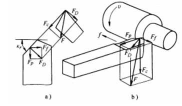
Figure 1-3-9 Decomposition of Cutting Forces
3. Feed force F" is the component of the total cutting force acting along the feed direction. This force, aligned with the feed direction in the base plane, is applied to the machine tool's feed mechanism. It serves as a key parameter for calculating and verifying the power, strength, and rigidity of the machine tool's feed system.
As shown in Figures 1-3-9, the relationship between the total cutting force F and its three component forces is

What is Cutting Power ?
The power consumed during the cutting process is termed cutting power pm. This power equals the sum of the power consumed by the cutting force Fc and the feed force Ff. Since the counterforce Fp does not displace, it consumes no power. Therefore, the cutting power (W) is

where Fc is the cutting force (N);
oc — Cutting speed (m/s); F" — Feed force (N);
o' —feed rate (mm/s).
Generally, the power consumed by F₁ (accounting for approximately 1% to 2% of Pm) is significantly lower than that of Fc. Therefore, Equation (1-3-2) can be simplified as

After calculating pm using the above formula, to determine the power pE of the machine tool motor, divide pm by the transmission efficiency ηm of the machine tool (typically ηm = 0.75 to 0.85), i.e.

What is Empirical Formula for Cutting Force?
At present, the empirical formula for calculating cutting force in production can be divided into two categories: one is the exponential formula, the other is the calculation according to unit cutting force.
(1)The exponential formula for calculating cutting force has been widely adopted in practical production, expressed as
Oblique cutting refers to the cutting process where the tool's main cutting edge has an inclination angle λs=0, meaning the cutting edge does not form a right angle with the direction of cutting speed. Figure 1-3-7b illustrates the scenario during oblique planing, which also falls under the category of free cutting. In oblique cutting, the direction of chip flow on the main cutting edge will deviate from its normal
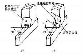
Figure 1-3-7 Right cutting and oblique cutting
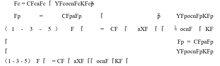
The coefficients CFc, CFp, and CF" are determined by the workpiece material and cutting parameters.
XFc、YFc、nFc、XFp、YFp、nFp
XF, YF, and nF represent the exponents of cutting depth ap, feed rate f, and cutting speed oc in the three component force formulas respectively.
In the formulas for KFc, KFp, and KF, the actual processing conditions differ from those used to derive empirical formulas.
When they are not consistent, the product of various factors to the correction factor of cutting component force.
Let KMF, KYOF, KkrF, KλSF, KrεF, and KTF represent the mechanical properties of the workpiece, the tool's rake angle, principal rake angle, cutting edge inclination angle, tip radius, and the correction coefficients for cutting forces under varying durability conditions, respectively. Denote KF as the combined coefficients KFc, KFp, and KFγ.
KF = KMFKYOFKkrFKλSFKrεFKTF (1 - 3 - 6)
The values of the coefficients and indices in equations (1-3-5), as well as the values of the modified coefficients in equations (1-3-6) under various cutting conditions, can be found in the relevant chapters of this book.
- Calculation of cutting force and power using unit cutting force
Unit cutting force p is the cutting force (N) per unit cutting layer nominal cross-sectional area (m2), so


In the formula, Fc is the cutting force (N);
AD — Nominal cross-sectional area of the cutting layer (m²);
bD — nominal width of the cutting layer (mm);
hD — nominal thickness of the cutting layer (mm);
Ap-cutting depth (mm);
『 — Feed (mm/r).
The unit cutting power pc is the power required to remove a unit volume of material per unit time (W/(m³/s)). Therefore

Q = 10 - 6ocap『
where Q is the material removal rate (m³/s);
oc-Cutting speed (m/s);
Pc — Cutting power (W);
Pc = Fcoc ≈ 10 - 6pap『oc (1 - 3 - 10)
Substituting Q and Pc into equations (1-3-9) yields
Therefore, if the unit cutting force p is known, the cutting force Fc can be calculated by Equation (1-3-8), and the cutting power Pc can be calculated by Equation (1-3-10).
The specific values of unit cutting forces can be found in relevant literature. Table 1-3-1 shows the unit cutting forces and unit cutting power of several commonly used materials cut by cemented carbide external turning tools.
Table 1-3-1: Common Metal Cutting Performance of Cemented Carbide External Turning Tools
unit cutting force and unit cutting power
| Workpiece material | Unit cutting force p / (N/mm²) 『 = 0. 3mm/r | Unit cutting power pc / (kW/ (mm3/S)) 『 = 0. 3mm/r | experiment condition | ||||||
| class | name | the name of a shop | Manufacturing and heat treatment status | hardness HBs | Tool geometry parameters | Cutting parameters range | |||
| steel | free cutting steel | Y40Mn | hot rolling | 202 | 1668 | 1668 × 10 - 6 | Yo = 15o kr = 75o λs = 0o bY1 = 0 Front blade surface with chip groove | vc = 90 ~ 150m/min ap = 1 ~ 5mm 『 = 0.1 ~ 0.5mm/r | |
| Carbon Knot Steel structure, alloy junction Steel section | Q235 - A | Hot rolled or normalized | 134 ~ 137 | 1884 | 1884 × 10 - 6 | ||||
| 45 | 187 | 1962 | 1962 × 10 - 6 | ||||||
| 40cr | 212 | ||||||||
| 40MnB | 207 ~ 212 | ||||||||
| 38crMoAlA | 241 ~ 269 | ||||||||
| 45 | Tempering (quenching and high Tempering) | 229 | 2305 | 2305 × 10 - 6 | Yo = 15o,kr = 75o,λs = 0o bY1 = 0. 1 ~ 0. 15mm Yo1 = -20° before the blade surface has a chip groove | ||||
| 40cr | 285 | ||||||||
| 38crsi | 292 | 2197 | 2197 × 10 - 6 | ||||||
| 45 | Tempering (quenching and low Tempering) | 44 (HRc) | 2649 | 2649 × 10 - 6 | |||||
| tool steel | 60si2Mn | hot rolling | 269 ~ 277 | 1962 | 1962 × 10 - 6 | Yo = 15o kr = 75o λs = 0o bYl = 0 Front blade surface with chip groove | |||
| T10A | anneal | 189 | 2060 | 2060 × 10 - 6 | |||||
| 9crsi | 223 ~ 228 | ||||||||
| cr12 | 223 ~ 228 | ||||||||
| cr12MoV | 262 | ||||||||
| 3cr2W8 | 248 | ||||||||
| 5crNiMo | 209 | ||||||||
| W18cr4V | 235 ~ 241 | ||||||||
| ball bearing steel | Gcr15 | anneal | 196 | 2109 | 2109 × 10 - 6 | ||||
| stainless steel | 1cr18Ni9Ti | quenching and tempering | 170 ~ 179 | 2453 | 2453 × 10 - 6 | Angle: 20°, Radius: 75°, Surface: λs = 0°, bY1 = 0, front blade surface with chip groove | |||
| Workpiece material | Unit cutting force p / (N/mm2) 『 = 0. 3mm/r | Unit cutting power pc / (kW/ (mm3/S)) 『 = 0. 3mm/r | experiment condition | ||||||
| class | name | the name of a shop | Manufacturing, heat treatment status | hardness HBS | Tool geometry | Cutting parameters range | |||
| iron casting | gray pig iron | HT200 | anneal | 170 | 1118 | 1118 × 10 - 6 | yo = 15o,kr = 75o,λs = 0o,by1 = 0, Flat cutting surface, no chip groove | vc = 1. 17 ~ 1.42m/s (70 ~ 85m/ min), ap = 2 ~ 10mm,『 = 0. 1 0. 1 ~ 0. 5mm/r | |
| nodular cast iron | QT450 - 10 | 170 ~ 207 | 1413 | 1413 × 10 - 6 | |||||
| malleable cast-iron | KTH300 - 06 | 170 | 1344 | 1344 × 10 - 6 | yo = 15o, kr = 75o, λs = 0o, by1 = 0, front blade surface with chip groove | ||||
| chilled cast iron | Roller for | case harden | 52 ~ 55 (HRC) | 3434 〔『 = 0 . 8〕 | 3434 × 10 - 6 | yo = 0o,kr = 12 ~ 14o,λs = 0o,B"1 = 0, Flat cutting surface, no chip groove | vc = vc = 0. 117m/s (7m/min), ap = 1 ~ 3mm,『 = 0.1 ~ 1.2mm/r | ||
| 3139 〔『 = 1〕 | 3139 × 10 - 6 | ||||||||
| 2845 〔『 = 1 . 2〕 | 2845 × 10 - 6 | ||||||||
| alufer | cast aluminium alloy | ZL110 | cast-on outwell | 45 | 814.2 〔yo = 15o〕 | 814.2 × 10 - 6 | yo = 15o, 25o , kr = 75o,λs = 0o, by1 = 0, Flat cutting surface, no chip flute | vc = 180m/ min, ap = 2 ~ 6mm,『 = 0. 1 0. 1 ~ 0. 5mm/r | |
| 706.3 〔yo = 25o〕 | 706.3 × 10 - 6 | ||||||||
| hard aluminum alloys | ZA12 | Tempering and aging | 107 | 833.9 〔yo = 15o〕 | 833.9 × 10 - 6 | ||||
| 765.2 〔yo = 25o〕 | 765.2 × 10 - 6 | ||||||||
| Copper and copper alloys | yellow metal | H62 | cold-drawing | 80 | 1422 | 1422 × 10 - 6 | Angle: 15°, Radius: 75°, Surface: λs = 0°, By1: 0°, Flat front blade surface, No chip flute | vc = 1.83m/s ( 110m/ min),ap = 2 ~ 6mm,『 = 0.1 0.1 ~ 0.5mm/r | |
| Workpiece material | Cutting force per unit p (N/mm²) 『 = 0 . 3mm/r | Unit cutting power pc / (kW/ (mm3/S)) 『 = 0 . 3mm/r | experiment condition | ||||||
| class | name | the name of a shop | Manufacturing, heat treatment status | hardness HBS | Tool geometry | Cutting parameters range | |||
| molybdenum | Pure molybdenum | powder metallurgy | 109 | 2413 | 2413 × 10— 6 | Yo = 20o,kr = 90o,λs = 0o,bY1 = 0. 15mm,Yo1 = — 5o, Front cutting edge with chip groove | vc = 40m/min ap = 1 ~ 5mm, 『 = 0.1 ~ 0.4mm/r | ||
2. No cutting fluid.
What are the Factors affecting cutting force?
Table 1-3-2 Factors affecting cutting force
| influencing factor | explain |
| Workpiece material | The higher the strength and hardness of the workpiece material, the greater the cutting force required. Materials with a higher tendency to work hard during machining will require more force. The addition of elements like sulfur and lead to the workpiece (such as in machinable steel) reduces cutting force. When machining brittle materials like cast iron, the minimal plastic deformation in the cutting layer results in low work hardening, leading to less friction between the fragmented chips and the tool face, thus reducing cutting force. Additionally, variations in heat treatment conditions and microstructural composition of the same material can also influence cutting force levels. |
| Cutting depth ap, feed rate | As the cutting depth (ap) and feed rate (f) increase, the deformation resistance and friction force rise, consequently increasing the cutting force. However, their impacts on the cutting force differ: typically, doubling the cutting depth (ap) doubles the cutting force, whereas doubling the feed rate (f) only increases it by 68% to 86%. |
| cutting speed vc | When machining plastic metals, the effect of cutting speed vc on cutting forces exhibits a wavelike pattern. At low speeds (vc <50 m/min), as vc increases, the chip mound gradually grows, causing the tool's effective rake angle to progressively increase and resulting in a gradual decrease in cutting force. When vc continues to rise, the chip mound diminishes and eventually disappears, leading to an increase in cutting force. Beyond 50 m/min, increased cutting speed raises temperatures and reduces frictional forces, causing the cutting force to decrease again. When cutting brittle metal, the plastic deformation is very small, and the friction between chip and rake face is also small, so vc has little influence on cutting force |
| anterior angle Yo | A larger tool rake angle reduces deformation in the cutting layer, thereby decreasing cutting forces. The influence of rake angle on cutting forces diminishes with increasing cutting speed, as elevated temperatures during high-speed machining reduce friction, work hardening, and plastic deformation. When machining brittle metals like cast iron, the effect of rake angle on cutting forces becomes less significant. |
| tool cutting edge angle kr | When the nominal cross-sectional area of the cutting layer remains constant, an increase in kr leads to a greater nominal thickness and reduced deformation, consequently decreasing the cutting force Fc. However, when kr exceeds 60° to 75°, the increased radius of the cutting edge arc causes a slight rise in Fc due to its greater weight. As kr increases further, Fp decreases while F' rises significantly. |
| tool cutting edge inclination angle λs, | λs has no effect on Fc when it varies over a wide range (from-40°C to +40°C), but as λs decreases, Fp increases and F' decreases. |
| influencing factor | explain |
| Tip radius Yε | The effect of Yε on Fc is small. When Yε increases, Fp will increase |
| cutter material | The friction coefficient between the tool and the workpiece directly affects the cutting force. Under the same cutting conditions, the cutting force of high-speed steel tool is the largest, followed by cemented carbide, and the smallest is ceramic tool. |
| cutting fluid | The higher the lubrication performance of cutting fluid, the more obvious the reduction of cutting force |
| cutting-tool wear | When the tool face is worn, the contact friction increases and the cutting force increases; when the tool face is worn to form a crescent-shaped depression, the cutting force decreases due to the increased rake angle |
How to Measure the cutting force?
There are two primary methods for measuring cutting component forces. The first category involves indirect measurement techniques, such as attaching strain gauges to rolling bearing outer rings, using displacement meters to measure spindle or tool holder deformation, monitoring drive motor power consumption or slip rates, and measuring hydrostatic bearing pressure. These methods allow indirect determination of cutting force magnitude. The second category employs direct measurement methods, primarily utilizing force gauges. Common types include strain gauge and piezoelectric force gauges. Their working principle involves detecting deformation in the gauge's elastic components caused by cutting forces, or converting electrical charges generated by piezoelectric crystals to measure individual cutting component forces.
(1) Resistance strain gauge force gauge
This measuring instrument has the characteristics of high sensitivity, large range, can be used for static and dynamic measurement, and high measurement accuracy.
The resistive elements commonly used in measuring instruments are called strain gauges. Multiple strain gauges are tightly attached to different stress points on the elastic components of the measuring instrument, each connected to form an electrical bridge (see Figure 1-3-10). When subjected to cutting forces, the strain gauges deform along with the elastic components, altering their resistance values and disrupting the bridge's balance. This generates an output current proportional to the magnitude of the cutting force. After amplification and calibration, the values of the three-directional cutting component forces can be accurately measured.
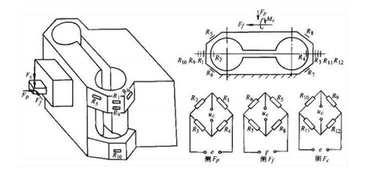
Figure 1-3-10 Layout of eight-sided ring lathe force gauge and strain gauge
(2) Piezoelectric Force Gauge
This high-precision device features superior sensitivity, high rigidity, and excellent self-resonance frequency. It demonstrates outstanding linearity, strong interference resistance, and zero inertia, making it particularly suitable for dynamic force measurement and instantaneous force detection. However, its humidity sensitivity is a notable limitation. When continuously measuring stable or minimally varying forces, the system may experience zero-point drift caused by charge leakage, which can compromise measurement accuracy.
Piezoelectric force gauges operate through the piezoelectric effect in quartz crystals or ceramic materials. When subjected to force, these components generate surface charges whose magnitude is proportional to the applied pressure, regardless of the crystal's size. A charge amplifier converts these charges into corresponding voltage parameters, enabling precise measurement of force magnitude (see Figure 1-3-11a).
A multi-directional force sensor (see Figure 1-3-11b) is formed by mechanically arranging several quartz components in sequence. When force is applied to the sensor, it acts on the quartz plates. Due to the different cutting directions of the quartz crystals, the sensitivity varies in each force direction, thus enabling the separate measurement of each cutting component force.
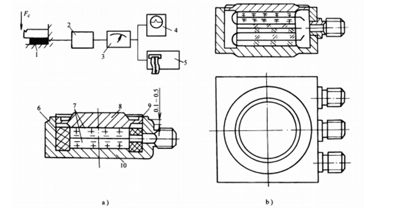
Figure 1-3-11 Piezoelectric sensor
a) Unidirectional force sensor and force measurement system b) Triaxial force sensor
1-Piezoelectric sensor 2-Charge amplifier 3-Peak voltmeter 4-Cathode ray oscilloscope
2-Light oscilloscope 6-PTFE sleeve 7-Chip 8-Cover 9-Electron beam weld 10-Base
Conclusion
In summary, cutting force and power are fundamental to the machining process. They directly impact tool life, surface finish, and part accuracy. By understanding how materials, tool geometry, and cutting parameters influence these forces, we can optimize for higher quality, greater efficiency, and reduced costs in every project.