
We will make the details of the cnc machining basic concepts .
What is the Basic Concepts of CNC Machining?
Contents
hide
1. Cutting Motion and Cutting Parameters
Cutting motion refers to the relative movement between the workpiece and the cutting tool. In different machining operations, this motion is a combination of simple linear and rotational movements. According to its function, the cutting motion can be divided into two categories (see Figure 1-3-1):
(1) Primary Motion
The primary motion is the basic relative movement between the workpiece and the tool that performs the actual cutting. It has the highest speed and consumes the most power. There is only one primary motion in the cutting process. It can be generated either by the workpiece or the tool, and can be rotary or linear.
The velocity of the primary motion is called the cutting speed, denoted by vc:
During external cylindrical turning, the primary motion is the rotation of the workpiece.
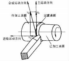
Figure 1-3-1 Cutting motion and workpiece surface in external turning
(2) Feed Motion
The feed motion continuously advances the layer of material to be cut into the cutting zone, allowing the formation of the entire machined surface. Feed motion usually has a lower speed and consumes less power than the primary motion. It may consist of one or more movements, and can be either continuous or intermittent.
In external turning, the feed motion is the continuous linear movement of the cutting tool parallel to the workpiece axis.
The velocity of the feed motion is called the feed rate, denoted by vf
and its unit is mm/s or mm/min. Feed rate may also be expressed as:
Feed per revolution (f): mm/r
Feed per stroke: mm/st
Feed per tooth (fz): mm/z
Before the feed motion begins, the intermittent motion that brings the cutting tool into the workpiece is called the approach motion, and its amount is known as the depth of cut (ap).
In external turning (see Figure 1-3-2), the cutting depth ap is the vertical distance between the machined and unmachined surfaces of the workpiece:
ap = (dw - dm) / 2
Where:
dw — Diameter of the unmachined surface (mm)
dm — Diameter of the machined surface (mm)
The cutting parameters collectively refer to the cutting speed vc, feed rate f, and cutting depth ap. These parameters must be chosen based on workpiece material, tool material, and technological requirements.
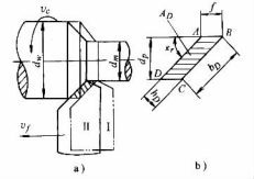
Figure 1-3-2 Cutting parameters and cutting layer parameters
2. Workpiece Surfaces in Cutting
During the cutting process, three types of surfaces are defined on the workpiece (see Figure 1-3-1):
(1) Surface to be machined: The portion of the workpiece that will be removed by cutting.
(2) Machined surface: The surface already generated after cutting by the tool.
(3) Transition surface: The surface currently being cut by the tool’s cutting edge, always located between the machined and unmachined surfaces.
3. Parameters of the Cutting Layer
The cutting layer is the layer of material removed by one cutting action of the tool. In external turning, the cutting layer is the metal layer removed when the workpiece makes one revolution and the cutting edge advances one feed rate, as shown in Figure 1-3-2 (ABCD).The size and shape of the cutting layer are represented by parameters measured in the plane passing through a selected point on the cutting edge and perpendicular to the cutting speed vc.
(1) Nominal Thickness of the Cutting Layer (hD)
The nominal thickness is the dimension of the cutting layer measured perpendicular to the transition surface — that is, the distance between two adjacent transition surfaces. It represents the cutting load per unit length of the cutting edge.
For external turning, if the main cutting edge is a straight line:
hD = f sin kr
Where: kr — Principal cutting edge angle
(2) Nominal Width of the Cutting Layer (bD)
The nominal width is the dimension of the cutting layer measured along the transition surface, representing the effective working length of the cutting edge. For a straight main cutting edge in external turning:
bD = ap / sin kr
(3) Nominal Cross-Sectional Area of the Cutting Layer (AD)
The nominal cross-sectional area represents the actual cross section of the material being removed, given by:
AD = hD × bD
This parameter indicates the amount of material removed per cutting stroke and directly affects the cutting force and power requirements.
Summary of Section 1
Section 1 establishes the fundamental kinematic and geometric concepts of the cutting process. It defines how cutting motions are classified, how surface layers are formed, and how the cutting parameters — speed, feed, and depth — determine material removal characteristics. These principles serve as the theoretical foundation for analyzing cutting deformation, chip formation, and power calculations in subsequent sections.