What is Metal Deformation in Cutting Process?
Metal deformation in the cutting process is the physical change a material undergoes when shaped by a tool. Governed by shear stress and plastic flow, it creates chips in three distinct zones. Mastering this process is essential for achieving precise dimensions, superior surface quality, and optimal tool life
Experimental and theoretical studies show that the formation process of chip is a plastic deformation process dominated by slip caused by the cutting layer being squeezed by the tool's rake face. This process can be described by Figure 1-3-3, which shows the deformation of plastic material.

I. Formation of metal material chips
When the tool's rake face pushes against the cutting layer, a stress field forms within it. The closer to the cutting edge, the greater the stress becomes. By identifying points where
shear stress τ reaches the material's yield strength τs within this stress field, we can plot curve OA. Since τs equals τs here, the workpiece begins shear slip along OA, which is called the initial slip line.
When a point P in the metal layer approaches the cutting edge and reaches position 1, its shear stress reaches the material's yield strength τs. As point 1 moves forward along OA, it undergoes slip, causing it to flow to point 2. The slip amount is 2/−2. During plastic deformation, strengthening occurs, requiring continuous stress τincreasing for further slip.
As point P continues moving forward under the tool's compression, the increasing shear stress drives continuous slip, as shown by 3/−3 and 4/−4 in Figure 1-3-3. Upon reaching point 4, the workpiece's flow direction aligns parallel to the rake face, halting slip. This segment OM is termed the final slip line.
Thus, materials in the cutting layer transform into chips through shear deformation from OA to OM, commonly known as the first deformation zone. The shear line in this zone intersects the free surface at a 45° angle. In the general cutting speed range, the width of this deformation zone is only 0.02 ~ 0.2mm, so it can be regarded as a shear plane, called shear plane
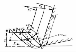
Figure 1-3-3 Slipping of metal in the first deformation zone
When the metal in the cutting layer undergoes shear slip and forms chips that flow
along the rake face, these chips are further compressed by the rake face, creating intense friction that causes additional deformation. This process forms the 'deformation zone'. Tool wear and chip accumulation primarily result from the deformation within this zone.
During machining, the processed surface of the workpiece undergoes significant deformation due to compression and friction from the rounded cutting edge and rake face. This deformation zone is referred to as the III deformation zone. The intense deformation leads to the formation of a workpiece surface hardened layer, generating residual surface stresses and potentially microscopic cracks. These defects can severely compromise both the surface finish quality and service performance of the workpiece.
Figures 1-3 illustrate the approximate locations of the three deformation zones during cutting. As most plastic deformation occurs in Zone I, the cutting deflection is primarily determined by this zone.

Figure 1-3-4 Three deformation zones during cutting
II. What is built-up edge?
When cutting plastic metal at medium or low cutting speed, it is often found that a small piece of very hard metal adheres to the front face of the cutting edge and cuts instead of the front face and cutting edge. This is the chip deposit (see Figure 1-3-5).
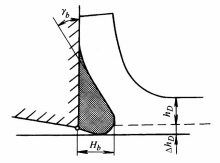
Figure 1-3-5 Chip Accumulation
(1) Formation Mechanism of Chip Accumulation Bump
During machining, intense pressure between the cutting edge and chips, combined with elevated temperatures, creates a stagnation layer at the chip base. Under specific pressure and temperature conditions, this stagnation layer separates from the chip and adheres (cold welding) to the cutting edge, forming the initial chip accumulation bump.
As chips continuously flow out, new stagnation layers gradually accumulate on the cold-welded layer. This sequential layer-by-layer buildup causes the bump to progressively expand. When reaching a critical height, changes in chip-edge contact dynamics and mechanical stress patterns halt further growth. Sudden impacts, vibrations, or variations in cutting forces during operation may trigger localized fractures or complete detachment of the accumulated chip layer.
(2) The influence of chip deposits on the cutting process.
The influence of chip deposits on the cutting process has both advantages and disadvantages. The advantages are:
- The hardness of scale is very high (generally 2 ~ 3 times that of the processed material). When it covers the cutting edge, it can replace the cutting edge for cutting and have a certain protective effect on the cutting edge.
- The actual rake angle of the tool is increased by the chip tumor (see Figure 1-3-5), which can reduce the cutting force. The adverse effects of scaling on the cutting process are:
- The front end of the chip tumor extends beyond the cutting edge, increasing the nominal thickness of the cutting layer (the increase value is ΔhD). Because the generation, growth and shedding of the chip tumor is periodic, ΔhD is changing, which may cause vibration.
- When chip pockets break apart, some detached fragments are carried away by the chips, while others flow into the tool-workpiece contact zone, forming 'plough grooves' on the workpiece surface and making it rough. The fragments may also embed into the workpiece surface, creating hard particles that accelerate tool wear.
(3) Measures to suppress or avoid chondroma
- Control the cutting speed during machining, try to use very low or very high cutting speed, avoid the speed range that produces chip deposits.
- The better the plasticity of the workpiece material, the greater the plastic deformation during cutting, and the easier it is to form chip deposits. Therefore, in order to suppress the formation of chip deposits, the material can be normalized or tempered to increase hardness and reduce plasticity.
- Increasing the tool front angle, reducing the feed, improving the surface grinding quality of the tool, and selecting cutting fluid with good lubrication performance can also reduce or inhibit the generation and development of chip deposits.
III. What is Shape of Chips?
During the cutting process, due to the different material of the workpiece, the geometric Angle of the tool, cutting parameters and so on, the deformation degree of the chip is also different, so the type of chip produced is different. The common chip types mainly include the following four (see Figure 1-3-6):
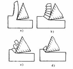
Figure 1-3-6 Types of chips
Strip-shaped chips (Fig. 1-3-6a)
exhibit elongated, ribbon-like morphology. The base layer in contact with the tool's cutting edge remains smooth without cracks, while the outer surface appears velvety. These chips typically form during plastic metal machining when combined with thin cutting thickness, high cutting speeds, and a large tool rake angle. The cutting process demonstrates stable operation with minimal force fluctuations, resulting in low surface roughness on machined workpieces. However, particular attention should be paid to chip breakage during machining.
Crushed chips (Fig. 1-3-6b)
maintain a continuous profile with greater deformation than strip-shaped chips. The base layer exhibits localized cracks and a serrated surface. These chips typically form under low cutting speeds, small tool rake angles, substantial cutting thickness, and machining medium-hardness plastic metals. During formation, the cutting force fluctuates, resulting in higher surface roughness on the workpiece.
Unit Chips (Fig. 1-3-6c)
When shear stress exceeds the metal's ultimate strength on the shear plane of fracture chips, cracks penetrate the chip thickness, forming trapezoidal unit chips. This phenomenon predominantly occurs with materials exhibiting low tool rake angles, slow cutting speeds, and poor plasticity. During machining, such chips exhibit greater cutting force fluctuations and result in inferior surface quality of the workpiece.
Brittle Chip Shedding (Fig. 1-3-6d)
When machining brittle metals, the material's poor plasticity and low tensile strength cause chips to fracture prematurely without sufficient deformation, forming irregular, fragmented debris. This results in significant cutting force fluctuations concentrated at the cutting edge, which not only risks tool damage but also produces a high surface roughness on the workpiece. Therefore, in production
It is necessary to avoid it, and the method is to reduce the cutting thickness, so that the chip is needle and sheet, and to increase the cutting speed appropriately, so as to increase the plasticity of the workpiece material.
IV. What is the concept of free and non-free cutting, right angle and oblique cutting?
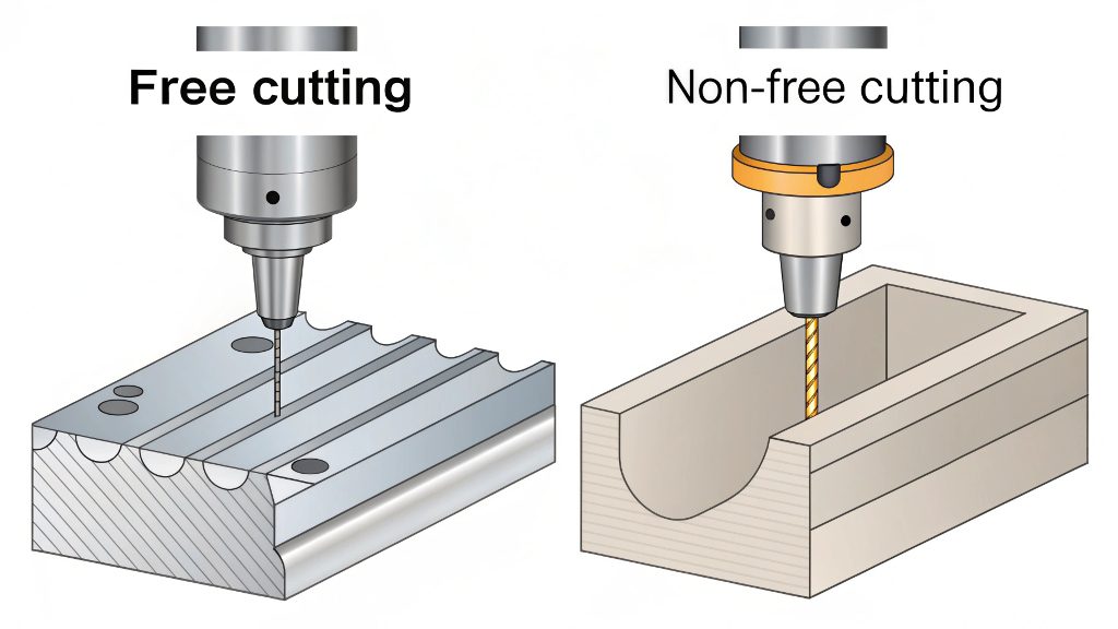
In machining operations, free cutting refers to a scenario where only a single straight cutting edge is engaged in the process. The defining characteristics of this method include: chips flowing in a uniform direction across the cutting edge, and metal deformation occurring primarily within a two-dimensional plane.
Conversely, when a tool's cutting edge is curved or involves multiple cutting edges (including primary and secondary cutting edges) simultaneously performing the entire cutting process, this is termed non-free cutting. The defining characteristic is that the
metal removed at the junctions of these cutting edges interferes with each other, resulting in more complex metal deformation that occurs in three-dimensional space. For example, during external cylindrical turning, secondary cutting edges also participate in the process alongside the primary cutting edge, making it a case of non-free cutting. In most practical applications, multi-edge tools predominantly employ this type of non-free cutting during machining operations.
Right-Angle Cutting vs. Inclined-Angle Cutting
Right-angle cutting refers to the cutting process where the tool's main cutting edge has a zero inclination angle λs. This configuration forms a right angle between the cutting edge and the direction of the cutting speed, hence it is also called orthogonal cutting. Figure 1-3-7a shows a schematic diagram of right-angle planing, which represents right-angle cutting in a free-cutting state. The chip flow direction in this scenario aligns with the normal direction of the cutting edge.
Oblique cutting refers to the cutting process where the tool's main cutting edge has an inclination angle λs=0, meaning the cutting edge does not form a right angle with the direction of cutting speed. Figure 1-3-7b illustrates the scenario during oblique planing, which also falls under the category of free cutting. In oblique cutting, the direction of chip flow on the main cutting edge will deviate from its normal
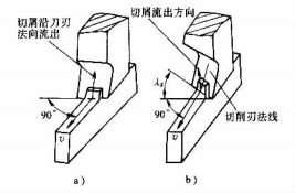
Figure 1-3-7 Right cutting and oblique cutting
Conclusion
Understanding metal deformation, chip formation, and built-up edge is not just theory; it directly determines part quality, tool longevity, and cost-efficiency in every CNC machining project.
Tired of inconsistent quality and communication issues? Stop letting preventable machining problems dictate your success. At Worthy, our experienced engineers master these principles to deliver 100% inspected, high-precision parts on your schedule.