What Factors Affect the CNC Machining Parts Quality?

Section 1 What is Machining Accuracy?
I. Machining accuracy and original error
1. What is Machining Accuracy

The machining quality of parts is the basis to ensure the quality of mechanical products. The machining quality of parts includes the machining accuracy of parts and the machining surface quality of parts.
The so-called machining accuracy refers to the degree of conformity between the actual geometric parameters (size, shape and mutual position between surfaces) and the ideal geometric parameters of the parts after machining. The higher the degree of conformity, the higher the machining accuracy.
Processing error refers to the deviation degree of the actual geometric parameters (dimension, shape and mutual position between surfaces) of the parts after processing from the ideal geometric parameters.
Processing accuracy and processing error are evaluated from two different angles to evaluate the geometric parameters of the processed parts. The low and high of processing accuracy is expressed by the large and small of processing error.
The machining accuracy of a part encompasses three key aspects: dimensional accuracy, form accuracy, and positional accuracy. These three elements are interconnected. Typically, form tolerances should be confined within positional tolerances, while positional errors must remain within dimensional tolerances. When high dimensional accuracy is required, corresponding positional and form accuracies must also meet stringent standards. However, when form accuracy demands are prioritized, the corresponding positional and dimensional accuracy requirements may not necessarily be as strict, depending on the functional requirements of the part.
Generally, higher machining precision of components typically results in higher processing costs and lower productivity. Therefore, designers should establish appropriate machining accuracy specifications based on the component's functional requirements. Process engineers must then implement suitable manufacturing methods that meet design specifications and production conditions, ensuring machining tolerances stay within acceptable limits while maximizing productivity and minimizing costs.
2. What is Original error?
In mechanical processing, the complete system formed by machine tools, fixtures, cutting tools, and workpieces is called the process system. The occurrence of machining errors is due to the existence of many error factors in the process system before and during machining, collectively referred to as original errors. The original errors of the process system mainly include:
(1)Principle error
The error caused by the approximate forming motion or the approximate blade profile.
(2)Adjustment Error
The purpose of adjustment is to achieve the correct relative position between the tool and the workpiece. Since adjustment can not be absolutely accurate, adjustment error is generated. There are two basic ways to adjust the process system, namely the trial cutting method and the adjustment method.
In single-piece and small-batch production, the trial-cutting method is widely adopted. The adjustment errors during trial-cutting primarily stem from measurement inaccuracies, displacement deviations in machine tool feed mechanisms, and deformation caused by force in the manufacturing process. For mass production, the adjustment method becomes predominant. The adjustment errors in this approach depend not only on the aforementioned factors but also on the specific adjustment techniques: When using fixed-stroke mechanisms, errors relate to manufacturing tolerances, installation deviations, wear of components (such as travel stop blocks, template jigs, and cams), and the sensitivity of associated electrical, hydraulic, or pneumatic control systems. When employing sample pieces, templates, tool-setting blocks, or guide sleeves for adjustments, errors are influenced by the manufacturing and installation tolerances of these components, wear patterns, and measurement inaccuracies during the adjustment process.
(3)Clamping error
It is the sum of positioning error and clamping error.
(4)Measurement error
Measurement error is the error related to the measurement principle, manufacturing accuracy, measurement conditions (temperature, humidity, cleanliness, vibration, measurement force, etc.) and measurement technology level of measuring instruments and measuring instruments.
(5)Manufacturing error and wear of the fixture
This refers to the machining error of the positioning element, guiding element, tool setting element, indexing mechanism, fixture body, etc. of the fixture, the relative size and position error between the working surfaces of the above components after the fixture is assembled, as well as the wear of the working surface of the fixture during the use.
(6)Manufacturing Tolerances and Tool Wear
Tool-type-specific impacts on machining accuracy vary significantly. For fixed-size tools (e.g., drills, reamers, keyway cutters, boring blocks, and circular broaches), dimensional accuracy directly determines workpiece dimensions. When using form tools (e.g., form turning tools, form milling cutters, and form grinding wheels), shape and installation errors directly affect workpiece geometry. Gear hobbing tools (e.g., gear hobbers, spline hobbers, and gear shaping tools) require precise cutting edge geometry and dimensions during hobbing operations. While general-purpose tools like turning tools, milling cutters, and boring tools maintain consistent machining accuracy during initial production, their wear over time will progressively compromise both dimensional and geometric precision of workpieces.
(7)Manufacturing, installation errors, and wear of machine tools.
Machine tool errors are the primary source of machining errors. These errors mainly include spindle rotation errors, guide rail alignment errors, transmission errors in internal linkage chains, and positional relationship errors between spindles and guide rails.
The spindle rotation error refers to the deviation between the actual rotation axis of the spindle and its ideal rotation axis. This error can cause shape and position errors, as well as surface waviness and roughness in the machined part.
Guidance error in machine tool guideways refers to the discrepancy between the actual movement direction of the moving components and their ideal direction. For linear guides, this error includes straightness deviations in both horizontal and vertical planes, as well as parallelism errors between front and rear guides. Such guidance errors can cause dimensional, geometric, and positional inaccuracies on machined surfaces. Factors like uneven wear of guide pairs, improper machine installation, or unstable foundations all contribute to increased guidance errors.
The transmission error of a transmission chain refers to the error of the relative motion between the transmission elements at the beginning and end of the transmission chain with internal connection. It is the main source of error affecting the machining accuracy of threads, gears, worms and other components machined according to the development principle.
The positional error between the spindle and guide rail of the machine tool (such as parallelism and perpendicularity) will cause the shape and position error of the machining surface.
(8) Deformation of the Process System Under Force
During Machining. When performing cutting operations, the process system composed of machine tools, cutting tools, fixtures, and workpieces undergoes deformation under the combined effects of cutting forces, clamping forces, and gravitational forces. This deformation alters the initially adjusted relative positions between tools and workpieces in static conditions, as well as the required geometric relationships for forming motions, thereby introducing machining errors. The process system's resistance to deformation is characterized by stiffness (k), defined as the ratio of the normal component Fy of the cutting force acting on the workpiece's surface to the tool's displacement y in that direction. Specifically,
The influence of process system stiffness on machining accuracy can be summarized in two aspects:
- In the cutting process, the stiffness of the process system will change with the change of the position of the cutting force, so the deformation of the process system will change accordingly, resulting in the shape error of the workpiece.
- When the shape error of the raw material is large or the hardness of the material is very uneven, the size of the cutting force will change greatly during the machining of the workpiece.
The deformation of the process system will also change with the change of the cutting force, thus causing the machining error of the workpiece. At this time, the workpiece is
The type of machining error caused by the piece is completely the same as the type of original shape and position error of the blank, so it is called "error reproduction".
Table 1-5-1 Key factors affecting shape accuracy and improvement measures
| Method to obtain shape accuracy | Main influencing factors | Improvement measures | |
| Forming Motion Method | method of loci | (1) Spindle rotation error (primarily caused by bearing errors, bearing clearance, mating parts errors, and assembly quality) (2) The guiding error of the machine tool guide rail (mainly caused by the manufacturing, installation error and wear of the guide rail) (3) The error of the mutual position relationship between the forming movements | 1) Enhance spindle component manufacturing precision: Utilize high-precision rolling bearings or hydrostatic/gas bearings; improve machining accuracy of housing support holes, spindle journal, and mating surfaces with bearings; optimize sliding bearing design by adopting short three-piece self-aligning bearings. For rolling bearings, implement angular alignment between front and rear units. 2) Pre-tension the rolling bearing 3) Prevent spindle rotation errors from being transferred to the workpiece: Use a fixed chuck to support the workpiece; ensure the tool or workpiece is floating connected to the machine spindle 1) Improve the manufacturing accuracy of the guide rail 2) Select appropriate guide rail configurations and combinations, and extend the mating length between the worktable and bed rails where feasible 3) Use liquid hydrostatic guide rails or appropriate oil scraping lubrication methods 4) Ensure the technical requirements of machine tool installation Improve the geometric accuracy of the machine tool |
| forming process | In addition to the error of forming motion itself and the error of mutual position relationship between forming motion, the manufacturing error, installation error and wear of tool will also cause the error of surface shape of machining | Improve the manufacturing accuracy, grinding quality, installation accuracy and wear resistance of the tool | |
| generating method | (1) The relationship between the speed ratio of forming motion is wrong (caused by manufacturing error and installation error of transmission components) (1) Tool manufacturing, grinding and installation error | 1) Shorten the transmission chain by using speed reduction transmission to improve the manufacturing and assembly accuracy of each transmission element, especially the end elements 2) Use a correction mechanism Select, resurface, and install tools according to technical specifications | |
| Unformalized movement method | Errors in measuring tools (such as standard rulers and platforms) and in testing methods | 1) Improve the accuracy of standard ruler and standard platform for testing 2) Use precision measuring tools and measuring instruments, and use the method of mutual inspection between the processed parts or between the parts and the check tool to improve the detection accuracy | |
(9)Thermal Deformation of Process Systems
During mechanical machining, process systems are affected by cutting heat, frictional heat, ambient temperature, and radiation heat, which can cause deformation. This deformation disrupts the correct relative positioning between workpieces and tools, resulting in machining errors. Thermal deformation significantly impacts machining accuracy, particularly in precision machining, large-scale component processing, and automated operations. In such scenarios, thermal deformation-induced machining errors typically account for 40% to 70% of the total machining errors.
(10)Deformation Caused by Residual Stress Redistribution
Residual stress, also known as internal stress, refers to the stress retained within a workpiece after external forces are removed. Components with residual stress exist in an unstable state, as their internal structures strongly tend to return to a stable stress-free condition. Even at room temperature, these components will gradually undergo this transformation until the residual stress is fully relieved. During this process, the parts will develop warping deformation, and their original machining precision will progressively diminish.
II. What are the Main factors affecting machining accuracy and improvement measures
1. Key factors affecting shape accuracy and improvement measures (see Table 1-5-1 and Table 1-5-2)
Table 1-5-2 Key factors affecting shape accuracy and improvement measures
| influencing factor | Improvement measures | |
| Process system deformation under force | 1) The stiffness of the process system varies greatly in different processing positions 2) Uneven blank allowance and uneven material hardness cause the change of cutting force 3) The influence of gravity, clamping force and inertia | 1) Improve the stiffness of the process system, especially the stiffness of the weak link 2) Use auxiliary support or foot knife holder 3) Optimize tool geometry and select appropriate cutting parameters to reduce tool resistance 4) Parts with high precision should be arranged for pre-processing 5) Implement balanced processing through appropriate clamping and machining methods |
| Process system thermal deformation | The thermal deformation of machine tool damages the static geometric accuracy of machine tool | 1) Remove, isolate, and cool the heat source to reduce its impact 2) Use the compensation method to balance the temperature field 3) Machine tool is turned on in empty state until thermal balance state is reached 4) Control ambient temperature |
| Deformation of workpiece during heating and machining, resulting in shape errors after cooling | 1) Perform sufficient and effective cooling 2) Reasonable selection of cutting parameters 3) Improve the clamping method of slender shaft and thin plate parts 4) Apply reverse deformation according to the thermal deformation pattern of the workpiece | |
| During prolonged machining operations, thermal deformation of the tool can cause shape errors in the machined surface. | 1) Fully cool 2) Reduce the cantilever length of the blade rod and increase the cross section of the blade rod | |
| Workpiece residual stress | 1) The machining process disrupts the equilibrium of residual stresses, resulting in shape changes of the workpiece due to their redistribution. 2) Components with residual stresses may lose their original precision under natural conditions due to stress relaxation and redistribution. | 1) Improve the structure of parts to reduce the residual stress of blanks 2) Perform time processing 3) Separate rough and finish processing 4) Replace cold straightening with hot straightening, and avoid straightening precision parts |
2. Key factors affecting dimensional accuracy and improvement measures (see Table 1-5-3)
Table 1-5-3 Main factors affecting dimensional accuracy and improvement measures
| Method for obtaining dimensional accuracy | Main influencing factors | Improvement measures |
| Trial method | (1) Measurement error (2) Feed mechanism displacement error (3) The influence of different thickness of cutting layer during trial cutting and formal cutting | Select appropriate measuring tools and methods, control measurement conditions, and perform multiple repeated measurements Improve the manufacturing accuracy and transmission stiffness of the feed mechanism, reduce the friction force, and adopt a new micro feed mechanism 1) Select tool materials with rounded edges and small radius to ensure precise sharpening of the cutting edge 2) Improve the stiffness of the process system |
| adjustment method | In addition to the influencing factors in the trial cutting method: (1) Manufacturing and installation errors in the timing mechanism, insufficient rigidity, and sensitivity issues in the control mechanism (2) Manufacturing and installation errors of samples and models (3) Error caused by measuring finite specimens (4) Tool wear (5) Workpiece clamping error (6) Thermal deformation of process system | Increase the stiffness of the limit mechanism and the sensitivity of the operating mechanism, and reduce the manufacturing and installation errors of the limit mechanism Improve sample and prototype manufacturing and installation accuracy Increase the number of test pieces Replace the tool or adjust the machine 1) Align the positioning reference with the process or design reference to enhance the manufacturing precision of the positioning surface and components 2) Reduce clamping deformation 1) Reduce heat source heating and isolate heat source 1) Balanced temperature field 3) Adopt thermal symmetry structure 4) Reasonable determination of adjustment size 5) Machine tool heat balance adjustment after processing 6) Control ambient temperature |
| Custom Tool Method | (1) Tool size error and wear | Improve the manufacturing accuracy of the tool, control the dimensional wear of the tool, and improve the wear resistance |
| (2) Tool installation error | Increase the position accuracy requirement for tool installation | |
| (3) Tool thermal deformation | Rational selection of cutting parameters, full cooling and lubrication | |
| Automatic control method | Sensitivity and reliability of control system | 1) Improve the sensitivity and reliability of the control system 2) Reduce the radius of the rounded blade edge to improve the stiffness of the process system |
3. Key factors affecting positioning accuracy and improvement measures (see Table 1-5-4)
Table 1-5-4 Key factors affecting positioning accuracy and improvement measures
| Mounting method | Main influencing factors | Improvement measures |
| Direct clamping | (1) Machine tool geometric error (2) Positioning error between the workpiece reference plane and the machining surface design reference | Improve the geometric accuracy of the machine tool 1) Improve the positional accuracy between the design datum and the positioning datum surfaces of the machined surface 2) Use the design datum of the machining surface as the positioning datum |
| Align formal attire clips | (1) Error of alignment method and measuring instrument (2) Error in aligning the base plane or baseline (3) Worker's technical level | 1) Use the alignment method and measuring instrument suitable for the machining accuracy 2) Improve the accuracy of aligning the reference plane with the baseline 3) Improve the technical level of workers |
| Jaw clamping | (1) Machine tool geometric error (2) The manufacturing and installation error of fixture and insufficient stiffness (3) Positioning error | Improve the geometric accuracy of the machine tool Improve the manufacturing, installation accuracy and stiffness of fixtures 1) Use the design reference of the processing surface as the positioning reference surface 2) Improve the manufacturing accuracy of the workpiece positioning reference plane 3) Improve the positional accuracy between the design datum and the positioning datum surfaces of the machined surface |
III What are the Analysis method of machining errors
1. Classification of processing errors
Various machining errors can be divided into:
(1)System error In the sequential processing of a batch of workpieces, the size and direction of the machining error remain constant or change according to a certain law, which is collectively called system error. The former is called constant system error, and the latter is called variable system error.
(2) Random error In the sequential processing of a batch of workpieces, the change of the size and direction of the machining error is random, which is called random error.
The original errors that cause various processing errors are shown in Table 1--5--5.
2. Analysis and calculation method of machining error
This method is applicable to the analysis and calculation of the influence of various system errors on machining accuracy. The analysis and calculation can be carried out as follows:
1) Identify the original errors that affect a certain processing error.
2) Establish the mathematical relationship between machining error and each original error through analysis, calculation or test and experiment.
3) Measure or calculate the value of each original error, substitute it into the mathematical relationship, and calculate each single processing error.
4) The total machining error is obtained by adding the algebraic machining errors of each single item.
3. Statistical analysis of machining errors
This method is only applicable to batch and mass production processed by the adjustment method. In mechanical processing, the two main statistical analysis methods used are distribution chart analysis and dot chart (x-R chart) analysis.
(1) Distribution map analysis method
1) Steps to draw a distribution diagram
a. Data collection: When processing a batch of parts, a random sample of n parts is selected for measurement. This selected batch is called a sample, with n being the sample size, typically ranging from 50 to 200 units.
Table 1-5: Original Errors Causing Various Processing Errors
| bias | random error | |
| Constant system error | Systematic variation | |
| 1) Principle error | 1) Tool dimensional wear (grinding wheel, | 1) Workpiece positioning error |
| 2) Adjustment errors in the process system (for | Carbide, end milling cutter, single edge boring cutter, etc.) | 2) Clamping error (for manual clamping) |
| One adjustment | 2) Thermal deformation of the process system (when the system reaches | 3) Measurement error (due to the transmission chain gap of the measuring instrument and measurement conditions |
| 3) Clamping error (for manual clamps | Before reaching thermal equilibrium | caused by instability and inaccurate readings |
| taut ) | 3) Multi-station machine with rotary worktable | 4) Adjustment errors in the process system (when multiple machine tools process the same |
| 4) Measurement errors (caused by instrument manufacturing, zero calibration inaccuracies, design principles, wear, etc.) | The division error and the installation error of the upper fixture | Batch processing of workpieces, a machine tool is adjusted many times to process a large number of workpieces) 5) Deformation of the process system under force (when machining allowance and material hardness are uneven) |
| 5) Manufacturing error and wear of fixture | 6) Deformation caused by residual stress | |
| 6) Tool manufacturing error | ||
| 7) Machine tool manufacturing, installation error and wear | ||
| 8) Process system deformation under force (processing | ||
| When the remaining material is uniform in hardness | ||
| 9) Thermal deformation of the process system (after reaching thermal equilibrium) | ||
b .Determine the number of groups k, group distance d, group boundary and group median. The number of groups k should be selected according to the sample size n (see Table 1-5-6).
Table 1-5-6: Selection of Grouping Number k
| n | 25 ~ 40 | 40 ~ 60 | 60 ~ 100 | 100 | 100 ~ 160 | 160 ~ 250 |
| k | 6 | 7 | 8 | 10 | 11 | 12 |
Interval
In the formula, R represents the range, defined as the difference between the maximum sample size x max and the minimum sample size x min, i.e., R = x max-x min.
The groups are grouped as
The median for each group is
c. Plot a frequency distribution graph with the workpiece size (median within the group) on the x-axis and frequency (number of parts in the same size group) on the y-axis.
d. Mark the tolerance band position on the distribution chart
e. Calculate the arithmetic mean x and standard deviation s of the sample
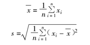
where xi is the size of each workpiece.
2) Application of distribution map analysis
a. Identification of Processing Error Characteristics: When the distribution curve closely resembles a normal distribution, it indicates the absence of systematic variation errors (or minimal impact) during processing. In such cases, further analysis can determine the presence of constant systematic errors by verifying if the sample arithmetic mean x coincides with the tolerance band center. If there is a significant deviation from the normal distribution curve, the distribution pattern can serve as a preliminary indicator for assessing the nature of variation systematic errors.
b. Calculate the process capability  coefficient Cp (where Cp_T represents part tolerance). If Cp> 1, it indicates sufficient upper process capability, but whether defects will occur during production depends on proper system adjustments. If Cp <1, defects will inevitably occur regardless of adjustments. In such cases, measures like precision machine tool upgrades, improved blank manufacturing accuracy, or switching to more advanced processing methods should be implemented to reduce random errors.
The distribution chart analysis method effectively demonstrates the combined influence of various random factors on machining accuracy. It enables clear differentiation between systematic errors (constant in magnitude and direction) and random errors. However, this approach has limitations:
1)It fails to account for the processing sequence of workpieces, making it unable to reveal error trends or distinguish between systematic and random variations;
2) The charts can only be generated after completing an entire batch of machining, thus lacking real-time capability to provide precision control data during the production process.
(2) Dot plot (x-R chart) analysis method
1) Steps to draw an x-R chart
- During the machining of a batch of workpieces, a small sample of n = 2 to 10 pieces is taken at regular intervals, and the arithmetic mean xi and range Ri of the small sample are calculated. After several time periods, k small samples can be obtained (usually k = 25).
- Plot the x-point diagram with the group number of small samples on the x-axis and the arithmetic mean x and range R of small samples on the y-axis, respectively.
c. Draw the centerline and upper/lower control lines on the x-chart and R-chart:
Upper control line Rs = D
Lower control line Rx = D
In the formula, A2, D1, and D2 are constants, which can be found in Tables 1 to 7.
Application of x-R Diagrams:
The x-axis represents the instantaneous distribution center, with the x-diagram primarily reflecting systematic errors and their trends. The R-axis indicates the instantaneous dimensional dispersion range, with the R-diagram showing random errors and their trends. These two diagrams should be used in conjunction. By analyzing the distribution patterns of the points, one can determine whether the manufacturing process is stable (i.e., whether fluctuations are within normal limits). The evaluation criteria are detailed in Table 1-5-8.
Table 1-5-7 A2, D1, D2 values
| c | A2 | D1 | D2 |
| 4 | 0 .73 | 2 .28 | 0 |
| 5 | 0 .58 | 2 . 11 | 0 |
| 6 | 0 .48 | 2 .00 | 0 |
Table 1-5-8 Normal and abnormal fluctuation indicators
| Normal Fluctuation | exceptional undulation |
| 1) No ideas beyond the control line | 1) Idea goes beyond the control line |
| 2) Most ideas fluctuate around the centerline, while a small portion remains stable. | 2) Ideas are dense near the midline |
| Near the control line | 3) The idea is dense near the control line |
| 3) There is no obvious regularity in the distribution of ideas | 4) More than 7 consecutive points on one side of the centerline 5) 10 out of 11 consecutive points are on the midline side 6) More than 12 out of 14 consecutive points appear on the midline side 7) More than 14 out of 17 consecutive points appear on the midline side 8) More than 16 out of 20 consecutive points appear on the midline side 9) Ideas tend to go up or down 10) Ideas fluctuate periodically |
Table 1-5-9 Economic accuracy of planar machining
| job operation | Tolerance Grade (IT) = | job operation | grade of tolerance (IT) | |
| Shaving and cylindrical milling, end face milling | wide | pare with a knife rub ========= | wide | 8 ~ 9 |
| Half-processed or primary processing | Semi-processed or single processing | 7 ~ 9 | ||
| refined | refined | 7 | ||
| precise | precise | 5 ~ 6 | ||
| broaching | Coarse grinding of cast surfaces and stamped surfaces | 5 | ||
| finish draw | 6 to 9 = Roll with steel balls or rollers 6 to 9 = Roll with steel balls or rollers | 7 ~ 10 | ||
Note: 1. This table applies to parts with size <1m and good structural rigidity, and the smooth machining surface is used as the positioning and measurement reference.
2. Under the same conditions, the machining accuracy of end milling is generally one level higher than that of cylindrical milling.
3. The precision milling machine is used for end milling.
4. Processing economic precision
The processing accuracy and surface roughness achievable through various machining methods (turning, milling, planing, grinding, drilling, boring, reaming, etc.) are all within specific ranges. The so-called economic machining accuracy refers to the achievable precision and surface finish under normal processing conditions—using equipment that meets quality standards, standard technical-grade workers, and process equipment without extended processing time.
The dimensional economic accuracy achievable by various machining methods is shown in Table 1-5-9 ~ Table 1-5-20, and the economic accuracy of shape and position achievable by various machining methods is shown in Table 1-5-21 ~ Table 1-5-30.
Table 1-5-10: Economic Accuracy of Surface Machining (mm)
| job operation | diameter | ||||
| ≤50 | > 50 ~ 120 | > 120 ~ 260 | > 260 ~ 500 | ||
| turnery | wide | 0 . 15 | 0 .20 | 0 .25 | 0 .40 |
| refined | 0 .07 | 0 . 10 | 0 . 13 | 0 .20 | |
| grinding | common | 0 .03 | 0 .04 | 0 .05 | 0 .07 |
| precise | 0 .02 | 0 .025 | 0 .03 | 0 .035 | |
Note: refers to the dimensional accuracy from the fingertip surface to the reference.
Table 1-5-11: Cost-effective precision for simultaneous machining of parallel surfaces (mm)
| Processing properties | Surface length and width | |||||
| ≤ 120 | > 120 ~ 300 | |||||
| Surface height | ||||||
| ≤50 | > 50 ~ 80 | > 80 ~ 120 | ≤50 | > 50 ~ 80 | > 80 ~ 120 | |
| Use a three-sided milling cutter to mill simultaneously | 0 .05 | 0 .06 | 0 .08 | 0 06 | 0 .08 | 0 . 10 |
Note: refers to the dimensional accuracy of the distance between two parallel surfaces.
Table 1-5-12 Economic accuracy of machining outer cylindrical surfaces
| c | grade of tolerance (IT) | |
| turnery | rough turn | 11 ~ 12 |
| Half a ride or a ride | 8 ~ 10 | |
| finish turning | 6 ~ 7 | |
| Precision turning, diamond turning | 5 ~ 6 | |
| grinding | coarse grind | 8 |
| finish grinding | 6 ~ 7 | |
| Precision grinding | 5 ~ 6 | |
| Grinding, Superfinishing | 5 | |
| Rolling, Diamond Siding | 5 ~ 6 | |
Table 1-5-13 Economic accuracy of hole machining
| job operation | grade of tolerance (IT) | |
| Drilling and hole enlargement with drill bit | 11 ~ 12 | |
| reaming | Expand | 12 |
| Drill or punch holes and expand them in one pass | 11 ~ 12 | |
| Drill or rough enlargement followed by precision enlargement | 9 ~ 10 | |
| reaming | Coarse Groove | 9 |
| finish ream | 7 ~ 8 | |
| Precision Screw | 7 | |
| bore a hole | heavy boring | 11 ~ 12 |
| right boring | 8 ~ 10 | |
| High-speed boring | 8 | |
| Precision boring | 6 ~ 7 | |
| Diamond boring machine | 6 | |
| broaching | Rough casting or punching | 7 ~ 9 |
| After rough or drilling, finish the hole | 7 | |
| grinding out | coarse grind | 7 ~ 8 |
| finish grinding | 6 ~ 7 | |
| Precision grinding | 6 | |
| Grinding, Honing | 6 | |
| Rolling, diamond pressing | 6 ~ 10 | |
Table 1-5-14 Economic accuracy of cylindrical deep hole machining
| job operation | grade of tolerance (IT) | |
| Use a hemp flower drill, flat drill, or ring hole drill to drill holes. | Drill rotation | 11 ~ 13 |
| Workpiece rotation | 11 | |
| Both the drill and the workpiece rotate | 11 | |
| counterboring | 9 ~ 11 | |
| Drill or boring a deep hole | Tool rotation | 9 ~ 11 |
| Workpiece rotation | 9 | |
| Both tool and workpiece rotate | 9 | |
| Bore with boring tool | 7 ~ 9 | |
| reaming | 7 ~ 9 | |
| job operation | grade of tolerance (IT) |
| grinding out | 7 |
| honing | 7 |
| grind | 6 ~ 7 |
Table 1-5-15 Economic accuracy of conical hole machining
| job operation | grade of tolerance (IT) | ||
| make a hole with an awl | Deep Cone | ||
| reaming | wide | 11 | |
| refined | 9 | ||
| bore a hole | wide | 9 | 9 ~ 11 |
| refined | 7 | ||
| reaming | motor-driven | 7 | 7 ~ 9 |
| hand movement | Above 7 | ||
| grinding out | Above 7 | 7 | |
| grind | 6 | 6 ~ 7 | |
Table 1-5-16 Economic accuracy of spline hole machining
| job operation | grade of tolerance (IT) |
| stick in | 9 |
| pull | 7 ~ 9 |
| rub | 7 ~ 9 |
Table 1-5-17 Economic accuracy of gear machining
| job operation | Accuracy class GB10095-88 GB10096—88 | ||
| Multi-pass gear hobbing (m = 1 to 20 mm) | 8 ~ 10 | ||
| Single-head hobbing (m = 1–20 mm) | Grinding wheel accuracy grade: A | AA A B C | 6 ~ 7 8 9 10 |
Table 1-5-18 Economic Accuracy of Forming Milling Tool Processing (mm)
| Surface length | rough mill | finish-milling | ||
| Ripper width | ||||
| ≤ 120 | > 120 ~ 180 | ≤ 120 | > 120 ~ 180 | |
| ≤ 100 | 0 .25 | — | 0 . 10 | — |
| > 100 ~ 300 | 0 . 35 | 0 .45 | 0 . 15 | 0 .20 |
| > 300 ~ 600 | 0 .45 | 0 .50 | 0 .20 | 0 .25 |
Table 1-5-19 Machining accuracy for metric threads
| job operation | Accuracy grade (GB197-63) | allowed band (GB197—81) | |
| turnery | external screw thread | 1 ~ 2 | 4h ~ 6h |
| internal thread | 2 ~ 3 | 5H、6H、7H | |
| Use comb cutter to turn threads | external screw thread | 1 ~ 2 | 4h ~ 6h |
| internal thread | 2 ~ 3 | 5H、6H、7H | |
| Tap the internal thread with a tap | 1 ~ 3 | 4H、5H ~ 7H | |
| Thread the outer thread with a round plate file | 2 ~ 3 | 6h ~ 8h | |
| Automatic spreader with round-toothed blade | 1 ~ 2 | 4h ~ 6h | |
| Cylindrical thread milling cutter | 2 ~ 3 | 6h ~ 8h | |
| Automatic open plate head with radial or tangential combing blades | 2 | 6h | |
| whirling | 2 ~ 3 | 6h ~ 8h | |
| Rub a foam board to make threads | 2 | 6h | |
| Rolling a tube into a thread | 1 ~ 2 | 4h ~ 6h | |
| Single or multiple wire grinding of threads | 1 or higher | 4h or more | |
| grind | 1 | 4h | |
Table 1-5-20: Economic Accuracy of spline Key Machining (mm)
| Maximum spline diameter | axle | Hole | ||||||
| Grinding roller milling cutter | Forming Mill | broaching | broaching | |||||
| accuracy | Precision before heat treatment | |||||||
| Spur width | Bottom circle diameter | Spur width | Bottom circle diameter | Spur width | Bottom circle diameter | Spur width | Diameter of the round base | |
| 18 ~ 30 | 0 .025 | 0 .05 | 0 .013 | 0 .027 | 0 .013 | 0 .018 | 0 .008 | 0 .012 |
| > 30 ~ 50 | 0 .040 | 0 .075 | 0 .015 | 0 .032 | 0 .016 | 0 .026 | 0 .009 | 0 .015 |
| > 50 ~ 80 | 0 .050 | 0 . 10 | 0 .017 | 0 .042 | 0 .016 | 0 .030 | 0 .012 | 0 .019 |
| > 80 ~ 120 | 0 .075 | 0 . 125 | 0 .019 | 0 .045 | 0 .019 | 0 .035 | 0 .012 | 0 .023 |
Table 1-5-21: Economic Tolerance for Flatness and Straightness
| job operation | grade of tolerance | = | job operation | grade of tolerance |
| Grinding, precision grinding, and fine scraping Grinding precision grinding, scraping, scraping, precision turning | 1 ~ 2 3 ~ 4 5 ~ 6 | Grinding, milling, planing, drawing, turning and milling, planing, turning, boring Various rough processing | 7 ~ 8 9 ~ 10 11 ~ 12 |
Table 1: Economic Accuracy of Machining 5-22 Type Surfaces
| job operation | Shape tolerance in diameter, in mm | ||
| economical | accessible | ||
| Process manually by template | 0 .2 | 0 .06 | |
| Machine machining | 0.1 | 0 .04 | |
| Scrape and plan with the underbar | 2 | 0 .40 | |
| Milling by underlines | 3 | 1 . 60 | |
| Use a template to mill on a machine | Control by machine | 0 .4 | 0 . 16 |
| Use the following system | 0 .06 | 0 .02 | |
| By the model car | 0 .24 | 0 .06 | |
| Forming Tool | 0.1 | 0 .02 | |
| Profile Milling | 0 .04 | 0 .02 | |
Table 1-5-23: Economic Accuracy of Cylindricity
| job operation | grade of tolerance | = | job operation | grade of tolerance |
| Grinding, Ultra-precision grinding Grinding, Honing, Precision Grinding, Diamond Boring, Precision Turning, Precision Boring | 1 ~ 2 3 ~ 4 | Grinding, Honing, Turning, and Honing, Honing, Reaming, and Boring Finish turning, boring, reaming, and tapping; finish boring and drilling Turn, boring, drilling | 5 ~ 6 7 ~ 8 9 ~ 10 |
Table 1-5: Economic Accuracy of Parallelism\
| job operation | grade of tolerance |
| Grinding, diamond precision machining, precision scraping | 1 ~ 2 |
| Grinding, honing, scraping, precision grinding | 3 ~ 4 |
| Grinding, coordinate boring, precision milling, precision planing | 5 ~ 6 |
| Grinding, milling, planing, drawing, boring, turning | 7 ~ 8 |
| Grinding, boring, turning, guide sleeve drilling, reaming | 9 ~ 10 |
| Various rough processing | 11 ~ 12 |
Table 1-5: Economic Tolerance for End Runout and Verticality
| job operation | grade of tolerance |
| Grinding, precision grinding, diamond precision machining | 1 ~ 2 |
| Grinding, precision grinding, precision scraping, precision turning | 3 ~ 4 |
| job operation | grade of tolerance |
| Grinding, scraping, honing, precision planing, precision milling, precision boring | 5 ~ 6 |
| Grinding, milling, planing, scraping, boring | 7 ~ 8 |
| Cars, semi-finishing, planing, boring | 9 ~ 10 |
| Various rough processing | 11 ~ 12 |
Table 1-5-26: Economic Accuracy of Coaxiality
| job operation | grade of tolerance | = | job operation | grade of tolerance |
| Grinding, honing, precision grinding, diamond precision machining Precision grinding, precision turning, internal cylindrical grinding and honing in a single setup, internal cylindrical grinding and boring in a single setup | 1 ~ 2 3 ~ 4 5 ~ 6 | Grinding, turning, boring, drawing, reaming, boring, drilling Various rough processing | 7 ~ 8 9 ~ 10 11 ~ 12 |
Table 1-5-27: Positional accuracy of holes with parallel axes
| job operation | The distance error between the two holes' axes or Distance error from the hole axis to the plane /mm | |
| Drill or swing-arm drilling | By underline | 0 .5 ~ 1 .0 |
| Use a drill jig | 0 . 1 ~ 0 .2 | |
| Drill or boring on a rotary arm drill | Use boring template | 0 .05 ~ 0 . 1 |
| Boring on a lathe | Underlined | 1 .0 ~ 3 .0 |
| On a angle iron fixture | 0.1~0.3 | |
| Boring on a coordinate boring machine | Use optical instruments | 0 .004 ~ 0 .015 |
| Boring on a diamond boring machine | — | 0 .008 ~ 0 .02 |
| Boring on a multi-axis group machine tool | Use boring template | 0 .05 ~ 0 .2 |
| Boring on a horizontal boring machine | By underline | 0 .4 ~ 0 . 6 |
| Use a ruler | 0 .2 ~ 0 .4 | |
| Use an inner diameter gauge or feeler | 0 .05 ~ 0 .25 | |
| Use boring template | 0 .05 ~ 0 .08 | |
| Read according to the indicator of the locator | 0 .04 ~ 0 .06 | |
| A program-controlled coordinate device | 0 .04 ~ 0 .05 | |
| By location template | 0 .08 ~ 0 .2 | |
| Use a ruler | 0 .05 ~ 0 . 1 | |
Table 1-5-28: Positional accuracy of holes with mutually perpendicular axes
| job operation | Verticality of the axis at 100mm length /mm | Axis displacement/mm | |
| Drill hole with a diamond drill | By underline | 0 .5 ~ 1 .0 | 0 .5 ~ 2 |
| Use a drill jig | 0.1 | 0 .5 | |
| Boring on a milling machine | rotary table | 0 .02 ~ 0 .05 | 0 . 1 ~ 0 .2 |
| Rotary indexing head | 0 .05 ~ 0 . 1 | 0 . 3 ~ 0 .5 | |
| Boring on a multi-axis combination machine | Use boring template | 0 .02 ~ 0 .05 | 0 .01 ~ 0 .03 |
| Horizontal boring machine for drilling holes in beds | By underline | 0 .5 ~ 1 .0 | 0 .5 ~ 2 .0 |
| Use boring template | 0 .04 ~ 0 .2 | 0 .02 ~ 0 .06 | |
| rotary table | 0 .06 ~ 0 . 3 | 0 .03 ~ 0 .08 | |
| Swivel workbench with dial | 0 .05 ~ 0 . 15 | 0 .05 ~ 0 . 1 | |
Table 1-5-29 Average economic accuracy of shape and position during machining on various machine tools
| Machine type | flatness | depth of parallelism (Processing surface) | verticality | |||
| Process the base surface | Processing surfaces | |||||
| slotting machine | Maximum insert length/mm | ≤200 | 0 . 05/300 | 0 . 05/300 | 0 . 05/300 | |
| > 200 ~ 500 | 0 . 05/300 | 0 . 05/300 | 0 . 05/300 | |||
| > 500 ~ 800 | 0 . 06/500 | 0 . 06/500 | 0 . 06/500 | |||
| > 800~ 1250 | 0 . 07/500 | 0 . 07/500 | 0 . 07/500 | |||
| surface grinder | stand Axis-Table Lying | — | 0 . 02/1000 | — | — | |
| Horizontal axis rectangular table (improves accuracy) | — | 0 . 009/500 | — | 0 . 01/100 | ||
| Horizontal axis frustum | — | 0.02/Workbench diameter: | — | — | ||
| Vertical axis circular platform | — | 0 . 03/1000 | — | — | ||
| shaper | 0 . 04/300 | ± 0 . 07/3000 | ± 0 . 07/3000 | ± 0 . 07/3000 | ||
Table 1-5-30 Positional accuracy of hole machining on combination machine tools and automated production lines
| Step Name | Diameter of the processed hole (mm) | Axial displacement of the hole/μm | ||
| Tool and bushing clearance/μm | ||||
| 30 | 100 | 150 | ||
| drill | 10 ~ 18 18 ~ 30 | 120 140 | 100 20 | 240 270 |
| reaming | 10 ~ 18 | 80 | 160 | 210 |
| reaming | 18 ~ 30 | 60 | 130 | 180 |
| reaming | 10 ~ 18 18 ~ 30 | 60 40 | 130 110 | 180 150 |
2. The axis displacement values shown in the table are suitable for the following conditions:
1) The tool rigidity is clamped on the spindle;
2) The drill bushing length is (2 ~ 2.5) d, with the tool extending 30mm beyond the bushing's end;
3) The positioning reference of the workpiece is a plane and two pin holes perpendicular to the plane.
Section 2 Surface Quality of Machining
Because the surface quality of machining has a great influence on the performance of machine parts such as wear resistance, contact stiffness, fatigue strength, mating properties, corrosion resistance and the stability of accuracy, so certain requirements should be put forward for the important surfaces of machine parts
Surface quality requirements.
The surface quality of processing includes two aspects:
(1) The geometric features of the machined surface mainly refer to the roughness, wave and texture direction of the machined surface.
(2) The physical properties of the processed surface layer mainly include the degree of work hardening and the depth of the cold hardened layer, the nature, size and distribution of the residual stress in the surface layer, and the changes of the metallographic structure of the processed surface layer.
I. Roughness of processed surface
1. Causes of surface roughness formation and measures to reduce it
(1) Causes of surface roughness in cutting
1) Geometric factors
The surface roughness caused by geometric factors is primarily determined by the residual area height (see Figure 1-5-1, labeled H).
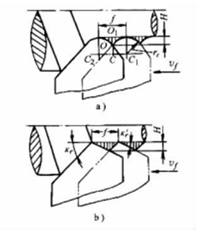
Figure 1-5-1 Residual area height during turning
2) Physical Factors The maximum actual surface roughness after machining often exceeds the residual area height, primarily due to various physical factors during the cutting process. These include chip accumulation, scale protrusions, plastic deformation of metal materials, and system vibrations
(2) Measures to reduce the surface roughness of cutting
1) Tool modifications: Increase the tool tip radius (rε), reduce the principal rake angle (kr) and auxiliary rake angle (k 'r); use a dressing insert with a length slightly longer than the feed length (k' r = 0°); enhance tool grinding quality by reducing surface roughness (polishing to Ra ≤1.25μm); adopt a larger rake angle. Process materials with high plasticity; control wear on auxiliary edges; select fine-grained cemented carbide for tool materials: use ceramic or titanium carbide-based carbides for carbon tool steel, diamond or mineral-ceramic tools for non-ferrous metals, and TiN-coated tools for high-speed steel.
2) Workpiece Requirements: When machining low-carbon steel and low-alloy steels, workpieces should undergo quenching and tempering treatment. For medium-carbon steel and medium-carbon alloy steels, if higher cutting speeds are used, the workpiece should have a pearlitic structure. If lower cutting speeds are employed, the workpiece should exhibit a lamellar pearlite with fine-grained ferrite. Easy-cutting steels must contain elements such as sulfur and lead. In gray cast iron, graphite particles should be of small size.
3) Regarding cutting conditions, use higher cutting speeds for plastic materials, reduce feed rate (see Figure 1-5-2); employ high-efficiency cutting fluids; improve machine tool movement accuracy, and enhance the rigidity of the process system.
(3) Causes of Surface Roughness Formation in Grinding and Reduction Measures The formation of surface roughness in grinding is caused by both geometric factors (residual)
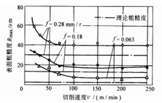
Figure 1-5-2 Effect of cutting speed and feed rate on surface roughness
Workpiece: 35 steel, Tool: YT15, Cutting depth: αp = 0.5mm
Area), there are also plastic deformation, softening, micro-melting and other physical factors, as well as the influence of vibration of the process system, so the main measures to reduce the surface roughness of grinding are:
1) Regarding grinding wheel characteristics: Use fine-grit wheels (typically with grit numbers below 80, commonly 46-60). Select appropriate hardness based on workpiece material and abrasive type (medium-soft wheels are generally preferred). Alumina or corundum wheels are suitable for steel components, silicon carbide wheels for cemented carbides, cast iron, brass, and aluminum, while synthetic diamond wheels are ideal for optical glass and ceramics. Boron nitride wheels can handle high-hardness and high-strength steels. For precision and form grinding, use tightly-structured wheels; medium-structured wheels for general grinding; and loose-structured wheels for rough grinding, surface finishing, internal cylindrical grinding, and heat-sensitive materials like soft metals or thin-walled workpieces. Additionally, increase wheel width by using larger-diameter wheels.
2) Regarding grinding parameters: Reduce workpiece speed while increasing grinding wheel rotation speed; implement smaller longitudinal feed rates and grinding depth (backcutting allowance), followed by non-feed smooth grinding. Perform meticulous wheel dressing with high precision in both static and dynamic balancing. Properly select cutting fluid types, concentration ratios, pressure levels, flow rates, and cleanliness standards. Enhance the spindle's rotational accuracy, ensure stable table movement, and improve the rigidity of the entire machining system.
2. Surface roughness achievable by various processing methods (see Table 1-5-31).
Table 1-5-31 Surface roughness achievable by various machining methods
| job operation | surface roughness Rα/μm | |||
| Auto gas cut, band saw or circular saw cut | 50 ~ 12 .5 | |||
| cut off | vehicle | 50 ~ 12 .5 | ||
| mill | 25 ~ 12 .5 | |||
| emery cutter | 3 .2 ~ 1 . 6 | |||
| Ream outer circle | rough turn | 12 .5 ~ 3 .2 | ||
| Semi-rough | metal | 6 . 3 ~ 3 .2 | ||
| nonmetal | 3 .2 ~ 1 . 6 | |||
| finish turning | metal | 3 .2 ~ 0 . 8 | ||
| nonmetal | 1 . 6 ~ 0 .4 | |||
| job operation | surface roughness Rα/μm | |||
| Ream outer circle | Precision turning (or diamond turning) | metal | 0 . 8 ~ 0 .2 | |
| nonmetal | 0 .4 ~ 0 . 1 | |||
| Turn end face | rough turn | 12 .5 ~ 6 . 3 | ||
| Semi-rough | metal | 6 . 3 ~ 3 .2 | ||
| nonmetal | 6 . 3 ~ 1 . 6 | |||
| finish turning | metal | 6 . 3 ~ 1 . 6 | ||
| nonmetal | 6 . 3 ~ 1 . 6 | |||
| Precision machine | metal | 0 . 8 ~ 0 .4 | ||
| nonmetal | 0 . 8 ~ 0 .2 | |||
| grooving | one stroke | 12 .5 | ||
| Trip 2 | 6 . 3 ~ 3 .2 | |||
| High-speed turning | 0 . 8 ~ 0 .2 | |||
| drill | ≤φ15mm | 6 . 3 ~ 3 .2 | ||
| > φ15mm | 25 ~ 6 . 3 | |||
| reaming | Coarse (with epidermis) | 12 .5 ~ 6 . 3 | ||
| refined | 6 . 3 ~ 1 . 6 | |||
| Downdraft (hole) | 3 .2 ~ 1 . 6 | |||
| Centered face | 6 . 3 ~ 3 .2 | |||
| reaming | Half-cut (first cut) | steel | 6 . 3 ~ 3 .2 | |
| yellow metal | 6 . 3 ~ 1 . 6 | |||
| reaming | finish ream (Secondary hinge) | iron casting | 3 .2 ~ 0 . 8 | |
| Steel, light alloy | 1 . 6 ~ 0 . 8 | |||
| Brass, bronze | 0 . 8 ~ 0 .4 | |||
| Precision hammers | steel | 0 . 8 ~ 0 .2 | ||
| light alloy | 0 . 8 ~ 0 .4 | |||
| Brass, bronze | 0 .2 ~ 0 . 1 | |||
| Cylindrical milling cutter milling | wide | 12 .5 ~ 3 .2 | ||
| refined | 3 .2 ~ 0 . 8 | |||
| precise | 0 . 8 ~ 0 .4 | |||
| job operation | surface roughness Rα/μm | |||
| End milling | wide | 12 .5 ~ 3 .2 | ||
| refined | 3 .2 ~ 0 .4 | |||
| precise | 0 . 8 ~ 0 .2 | |||
| High-speed milling | wide | 1 . 6 ~ 0 . 8 | ||
| refined | 0 .4 ~ 0 .2 | |||
| planing | wide | 12 .5 ~ 6 . 3 | ||
| refined | 3 .2 ~ 1 . 6 | |||
| precise | 0 . 8 ~ 0 .2 | |||
| Slot surface | 6 . 3 ~ 3 .2 | |||
| slotting | wide | 25 ~ 12 .5 | ||
| refined | 6 . 3 ~ 1 . 6 | |||
| bore a hole | heavy boring | 12 .5 ~ 6 . 3 | ||
| Semi-finishing | metal | 6 . 3 ~ 3 .2 | ||
| Not my group | 6 . 3 ~ 1 . 6 | |||
| right boring | metal | 3 .2 ~ 0 . 8 | ||
| nonmetal | 1 . 6 ~ 0 .4 | |||
| Precision boring (or Diamond boring) | metal | 0 . 8 ~ 0 .2 | ||
| nonmetal | 0 .4 ~ 0 .2 | |||
| High-speed boring | 0 . 8 ~ 0 .2 | |||
| broaching | refined | 1 . 6 ~ 0 .4 | ||
| precise | 0 .2 ~ 0 . 1 | |||
| broaching | refined | 0 . 8 ~ 0 .2 | ||
| precise | 0 .4 ~ 0 .025 | |||
| External cylindrical grinding, internal cylindrical grinding | Semi-refined (first processing) | 6.3~0.8 | ||
| refined | 0 . 8 ~ 0 .2 | |||
| precise | 0 .2 ~ 0 . 1 | |||
| Precision and ultra-precision grinding | 0 .050 ~ 0 .025 | |||
| Mirror grinding (external cylindrical grinding) | < 0 .050 | |||
| flat stone mill | refined | 0 . 8 ~ 0 .4 | ||
| precise | 0 .2 ~ 0 .05 | |||
| job operation | surface roughness Rα/μm | ||||
| honing | Coarse (single pass) | 0 . 8 ~ 0 .2 | |||
| Precision | 0 .2 ~ 0 .025 | ||||
| grind | wide | 0 .4 ~ 0 .2 | |||
| refined | 0 .2 ~ 0 .05 | ||||
| precise | < 0 .050 | ||||
| microstoning | refined | 0.8~0.1 | |||
| precise | 0 . 1 ~ 0 .05 | ||||
| Mirror finish (two passes) | < 0 .025 | ||||
| polishing | refined | 0.8~0.1 | |||
| precise | 0 . 1 ~ 0 .025 | ||||
| abrasive band polishing | 0 .2 ~ 0 . 1 | ||||
| Sand polish | 1 . 6 ~ 0 . 1 | ||||
| electropolish | 1 . 6 ~ 0 .012 | ||||
| thread machining | cutting | Tapping, tap, self-opening tap head | 3 .2 ~ 0 . 8 | ||
| Turn or comb cutter for turning and milling | 6.3~0.8 | ||||
| rub | 0 . 8 ~ 0 .2 | ||||
| grind | 0 . 8 ~ 0 .050 | ||||
| rolling | roll die | 1 . 6 ~ 0 . 8 | |||
| thread rolling die | 1 . 6 ~ 0 .2 | ||||
| Gear and spline machining | cutting | Smooth Roll | 3 .2 ~ 1 . 6 | ||
| Roll | 1 . 6 ~ 0 . 8 | ||||
| Insert | 1 . 6 ~ 0 . 8 | ||||
| adjustable cast iron planes | 3 .2 ~ 0 . 8 | ||||
| pull | 3 .2 ~ 1 . 6 | ||||
| shave | 0 . 8 ~ 0 .2 | ||||
| rub | 0.8~0.1 | ||||
| grind | 0 .4 ~ 0 .2 | ||||
| rolling | hot rolling | 0 . 8 ~ 0 .4 | |||
| cold rolling | 0 .2 ~ 0 . 1 | ||||
| shave | wide | 3 .2 ~ 0 . 8 | |||
| refined | 0 .4 ~ 0 .05 | ||||
| job operation | surface roughness Ra/μm | ||||
| surface rolling | 0 .4 ~ 0 .05 | ||||
| Fitter filing | 12 .5 ~ 0 . 8 | ||||
| clearage with grinding wheel | 50 ~ 6 . 3 | ||||
II. Physical quality of the processed surface layer
1. Cold work hardening of the surface layer
(1)Causes of work hardening
After machining, the surface layer of the processed metal of the workpiece is often harder than the base material, which is called work hardening.
Hardening is typically characterized by two parameters: the depth of the hardened layer (hd) and the degree of hardening (N). The vertical distance from the processed surface to the unhardened area (in micrometers) is denoted as hd. The parameter N represents the percentage increase in microhardness relative to the original microhardness H0, calculated as

where H denotes the microhardness of the machined surface (Gpa).
The depth of the hardened layer, denoted as hd, typically ranges from tens to hundreds of micrometers, with the hardening degree N reaching 120% to 200%.
During cutting and grinding processes, the cutting force induces significant plastic deformation in the workpiece's surface metal. This causes crystal lattice distortion, elongation, and fragmentation of metal grains, which impedes further deformation and enhances material strength and hardness. Simultaneously, cutting (grinding) temperature weakens the material, with higher temperatures triggering phase transformations.
The hardness variations on machined surfaces result from the combined effects of strengthening, weakening, and phase transformation. When strengthening dominated by plastic deformation occurs, the machined surface hardens. When weakening caused by cutting temperature prevails, the surface softens. Phase transformation dominates when specific conditions arise. For instance, during grinding hardened steel, annealing reduces surface hardness, while proper cooling may induce secondary quenching that increases surface hardness.
(2) Factors affecting processing hardening
1) Regarding cutting tools, a larger rake angle reduces the plastic deformation of the metal in the cutting layer, thereby decreasing the hardened layer depth (hd).
The larger the radius of the cutting edge's rounded edge (rn), the greater the compression of the machined surface during formation, resulting in higher work hardening (see Figure 1-5-3).
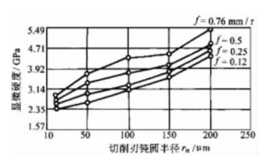
Figure 1-5-3 Effect of cutting edge blunt circle radius RN on work hardening
Workpiece: 45 steel
With the increase of the tool back face wear VB, the friction between the back face and the machined surface increases, and the depth of the machined hardening layer also increases.
2)Regarding workpiece characteristics: The greater the plasticity of the material, the higher the hardening index and the melting point, resulting in more severe hardening. For carbon structural steel, lower carbon content enhances plasticity and reduces hardening. Non-ferrous metals, with their lower melting points, tend to weaken more easily, thus exhibiting significantly less work hardening than steel.
3) Regarding cutting conditions, the influence of cutting speed on cold hardening is the result of combined force and thermal factors. Typically, the processing hardening decreases initially with increasing cutting speed, but increases again with higher cutting speed (see Figure 1-5-4).
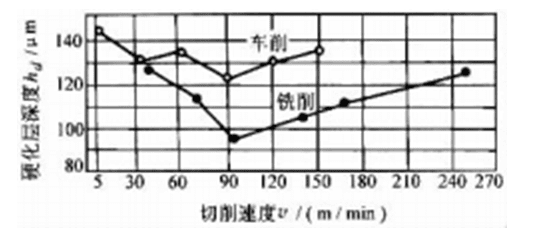
Figure 1-5-4 Effect of cutting speed on hardened layer depth
Tool: cemented carbide workpiece: 45 steel
Cutting parameters: αp = 0.5mm during turning.
= 0.14mm/r; during milling, αp = 3mm, αφ = 0.04mm/z
Increasing the feed will increase the cutting force and the range of plastic deformation zone, so the hardening degree increases accordingly (see Figure 1--5--3), while the change of cutting depth has no significant effect on the depth of hardened layer.
The effective cooling and lubrication measures can also reduce the depth of work hardening layer.
2. Residual stresses in the surface metal
(1) Causes of residual stress
1) Plastic deformation caused by mechanical stress
During the cutting process, the workpiece material in front of the cutting edge is compressed by the rake face, causing the metal layer about to become the machined surface layer to undergo compressive plastic deformation along the cutting direction. Due to the restraint of the undeformed metal layer, the residual tensile stress is formed.
In addition, the back face of the tool and the machined surface produce a large compression and friction, so that the surface metal produces tensile plastic deformation. After the tool leaves, the surface metal produces residual compressive stress under the action of the inner metal.
2) The compressive plastic deformation of the surface metal caused by thermal stress will produce residual tensile stress in the surface metal.
- Volume changes caused by phase transformation.
During machining, if the surface temperature exceeds the phase transition temperature, the surface metal structure may undergo phase transformation. If the microstructural changes result in an increase in the specific volume of the surface metal, residual compressive stress will develop; conversely, if the microstructural changes lead to a decrease in the specific volume, residual tensile stress will form.
The residual stress in the processed surface layer is the result of the combined action of the above factors, and its magnitude and sign are determined by the dominant factor.
When cutting carbon steel, residual tensile stress is usually formed in the machined surface layer, and its value can reach 0.78 ~ 1.08Gpa, and the depth of the residual stress layer can reach 0.40 ~ 0.50mm.
(2)Factors affecting residual stress
The factors affecting residual stress are relatively complex. Generally speaking, any factors that can reduce plastic deformation and reduce cutting temperature can reduce the residual stress of the machined surface.
- Regarding tool geometry:
As the rake angle transitions from positive to negative, the surface residual tensile stress diminishes while the residual stress layer deepens (see Figure 1-5-5). Under specific cutting parameters, employing a more negative rake angle with greater absolute value can induce residual compressive stress in the machined surface layer (see Figure 1-5-6).
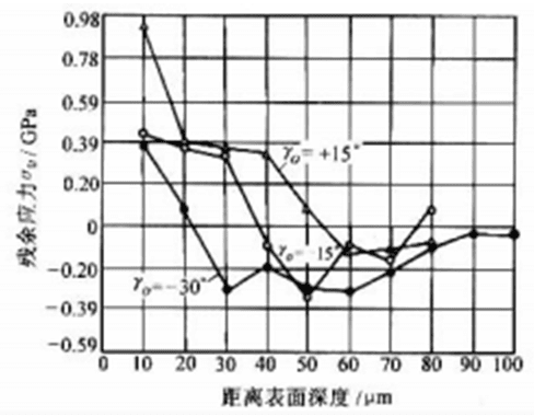
Figure 1-5-5 Effect of front corner on residual stress
Tool: cemented carbide workpiece: 45 steel cutting parameters:
v = 150m/min,ap = 0 . 5mm,『 = 0 . 05mm/r
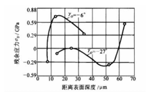
Figure 1-5-6 Effect of rake angle on residual stress during end milling
Tool: cemented carbide workpiece: 45 steel cutting parameters:
v = 320m/min,ap = 2 . 5mm,a『 = 0 . 08mm/Z
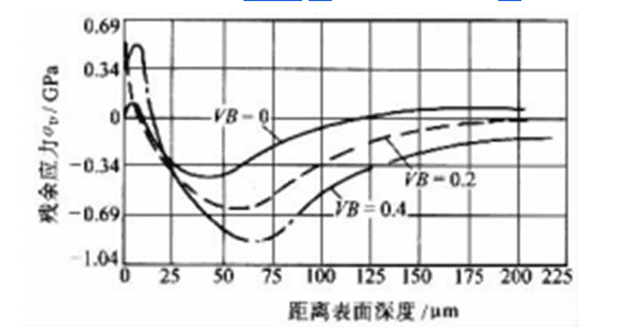
Figure 1-5-7: Influence of tool backface wear (VB) on residual stress
Tool: Single-tooth cemented carbide end milling cutter with a 0° axial rake angle.
Forward angle-15°, ao = 8°, kr = 45°, k'r = 5°
Workpiece: Alloy steel Cutting parameters: v = 55m/min
ap = 1 mm, a" = 0.13 mm/Z, without cutting fluid
When the wear amount VB of the tool back face increases, the residual tensile stress of the machined surface and the depth of the residual stress layer will increase accordingly (see Figure 1-5-7).
- Regarding workpiece aspects:
Materials with higher plasticity typically generate residual tensile stress after machining, with greater plasticity leading to higher residual tensile stress. When machining brittle materials such as gray cast iron, residual compressive stress forms in the surface layer.
When the wear amount VB of the tool back face increases, the residual tensile stress of the machined surface and the depth of the residual stress layer will increase accordingly (see Figure 1-5-7).
- Regarding cutting conditions:
The residual tensile stress on machined surfaces increases with cutting speed, while the depth of the residual stress layer decreases (see Figures 1-8). As cutting speed rises, the temperature also increases. When the cutting temperature exceeds the metal's phase transformation temperature, the situation changes. At this point, the magnitude and sign of residual stress depend on the changes in the surface microstructure.
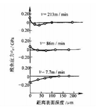
Figure 158 Effect of cutting speed on residual stress
Tool: Indexable cemented carbide tool, YO = 150
αO = αIO = 5°, λs = -5°, Kr = 75°,
KIr = 15°, rε = 0.8 mm, workpiece: annealed 45 steel
Cutting parameters: ap = 0.3 mm, 『 = 0.05 mm/r
No coolant
When the feed amount increases, the residual tensile stress on the machined surface of the workpiece and the depth of the residual stress layer will increase accordingly (see Figure 1-5-9).
In the case of annealed steel, the effect of cutting depth on residual stress is not significant, while in the case of 45 steel quenched and tempered, the surface residual tensile stress decreases slightly with the increase of cutting depth.
- Measurement of Residual Stress
The methods for measuring residual stress in surface layers can be broadly categorized into two types: physical and mechanical approaches. Physical methods utilize the inherent properties of materials to perform non-destructive testing, including X-ray, ultrasonic, magnetic, and photoelastic techniques. Among these, only X-ray methods enable quantitative measurements. Mechanical methods work by inducing deformation in components through residual stress imbalances, then calculating stress levels based on stress-strain theories. However, creating such stress imbalances requires progressively removing layers from components containing residual stress. Therefore, mechanical methods are not classified as non-destructive testing techniques.
4. Grinding burn and crack
(1)Grinding burn
It refers to the localized structural changes in a workpiece's surface caused by instantaneous high temperatures during grinding, resulting in oxidation and discoloration on specific areas. This process reduces material's wear resistance, corrosion resistance, and fatigue strength. In severe cases, cracks may develop.
There are two main forms of grinding burn on hardened steel parts:
- Backfire burn refers to the condition where the temperature in the grinding zone significantly exceeds the tempering temperature of steel but remains below the phase transition temperature, affecting the surface of the workpiece.
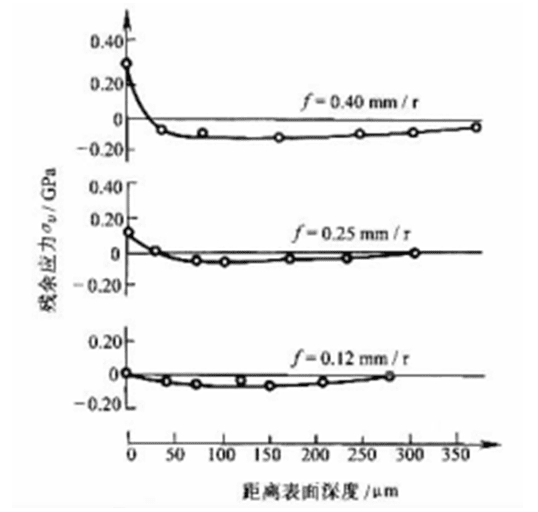
Figure 1-5-9 Effect of feed rate on residual stress
Tools and workpiece are shown in Figure 1-5-8. Cutting conditions: o = 86m/min.
"p = 2mm, no cutting fluid
The layer shows tempered martensite or tempered sorbite softening structure.
(2)Quenching Burn Damage
When the temperature in the grinding zone exceeds the phase transformation temperature Ac1, the surface layer of the workpiece transforms into austenite. Subsequently, rapid cooling from both the coolant and the workpiece's thermal conductivity leads to the formation of secondary quenched martensite within an extremely thin surface layer. The underlying layer then becomes tempered sorbite with significantly reduced hardness. This phenomenon is known as secondary quenching burn damage.
The main methods for judging grinding burns are:
1) Color Observation Method: As the temperature in the grinding zone rises, the thickness of the oxide film on the workpiece surface varies, resulting in different "tempered colors" such as yellow, straw yellow, brown, and purple. However, the absence of burn marks on the surface does not mean the surface layer is free from burn damage. This method of judgment has relatively low accuracy.
2) Acid Washing Method: This technique leverages the varying metallographic structures of steel components to differentiate their corrosion sensitivity. For example, normal tempered martensitic bearing steel appears gray after acid washing, turns black when severely backfire-damaged, and becomes white when subjected to secondary quenching damage. This method is commonly used in production for quality inspection.
3) Metallographic organization method: This method identifies burn types by observing changes in surface metallographic structures, offering high accuracy.
4) Microhardness method: The surface microstructure of the workpiece inevitably changes, so the observation of the hardness change can determine the type of burn and the depth of metamorphic layer. The disadvantage is that the specimen needs to be made.
(2) Grinding Cracks
When grinding workpieces such as carburized steel, tool steel, quenched high-carbon steel, and cemented carbides, fine surface cracks may develop. These cracks are typically shallow (0.03–0.05 mm), though severe cases can reach 0.25–0.5 mm. Their orientation generally runs perpendicular to the grinding direction or forms a network pattern.
Grinding cracks originate from defects developed during pre-grinding processes, including network carbides in the material surface, non-metallic inclusions, loose microstructures, compositional segregation, and quenching-induced deformation at grain boundaries. These cracks typically develop alongside surface burn marks. Grinding cracks form when residual tensile stress in the workpiece surface exceeds the material's tensile strength.
Grinding cracks are usually checked by fluorescent material method, iron powder method and dilute nitric acid corrosion method.
(3) Process approach to reduce grinding burn and crack
1) Select the right grinding wheel. For example, use one with coarser, softer particles and a looser structure. Replace it promptly when worn repair and maintain 。
2) Improve the cooling conditions during grinding, such as using internal cooling method; try to make the coolant penetrate into the grinding area.
3) Reasonable selection of grinding parameters, such as increasing the speed of the workpiece and using a smaller radial feed.
Section 3 Vibration in machining
I. Types and characteristics of cutting vibration
The vibration produced in machining mainly has two types: forced vibration and self-excited vibration (tremor).
(1)Forced vibration
It refers to vibrations induced by periodic external disturbance forces (either internal or external vibration sources within the process system). Its main characteristics are:
1) The frequency of forced vibration is the same as the frequency of the periodic interference force, or an integer multiple of it.
2) Except for the forced vibration caused by the inhomogeneity of the cutting process itself, the interference force is generally unrelated to the cutting process. When the interference force is eliminated, the forced vibration stops.
3) The amplitude of forced vibration depends on the amplitude of the disturbance force, the stiffness of the process system, and the damping. When the frequency of the disturbance force remains constant, the larger the amplitude of the disturbance force and the smaller the stiffness and damping of the process system, the larger the amplitude of forced vibration.
4) When the ratio of the frequency of the interference force to the natural frequency of the process system is equal to or close to 1, the system will produce resonance and the amplitude reaches the maximum value.
(2) Self-excited vibration (tremor)
Periodic vibration generated by internal excitation feedback in the machining process without periodic external force (relative to the cutting process). Its main characteristics are:
1) The frequency of self-excited vibration is equal to or close to the natural frequency of the system.
2) Whether the self-excited vibration can be generated and the size of its amplitude are determined by the comparison between the energy obtained by the system and the energy consumed by the damping in each vibration cycle.
3) Since the interference force to maintain the self-excited vibration is excited by the vibration (cutting) process itself, the interference force and energy replenishment process disappear immediately once the vibration (cutting) is stopped.
II. Forced vibration source and diagnosis
(1) Forced vibration source
1) Periodic changes in centrifugal force caused by unbalance of rotating parts on the machine tool, such as electric motor, grinding wheel, pulley, chuck, cutter disc, workpiece, etc.
2) The inhomogeneity of the cutting process itself, such as the periodic changes of cutting force caused by milling, turning and turning the surface of the workpiece with keyway.
3) Periodic changes in transmission force caused by defects in machine tool transmission elements, such as gears with inaccurate manufacturing or poor installation, uneven thickness of V-belts, joints of flat belts, dimensional and shape errors of bearing rolling bodies, and pressure pulsation of working fluid when hydraulic pump works.
4) Inertial impact generated when the direction of reciprocating moving parts changes.
5) Interference force from other external vibration sources.
(2) Diagnosis of forced vibration
1) On-site vibration acquisition and spectral analysis: During machining operations, sensors (such as accelerometers or force sensors) are deployed along vibration-sensitive directions near the workpiece. The collected vibration signals undergo spectral analysis to generate vibration spectra. The number of distinct peaks in the spectrum corresponds to the vibration frequency components present in the machining system.
2) Conduct environmental testing to identify external vibration sources. When the machine is stationary, collect vibration signals and perform spectral analysis. The resulting vibration frequency components will correspond to those of external interference forces. Compare these components with the vibration frequencies observed during actual machining operations. If they match exactly, the vibrations are confirmed to be forced vibrations originating from external sources. If the main vibration frequency components from actual machining differ from those of external interference forces, further idle running tests should be conducted.
3) Conduct a short-run test to identify internal vibration sources. The machine tool performs idle operation according to the motion parameters used in the machining site, collects vibration signals, and conducts spectral analysis. By comparing the spectral patterns obtained from the idle test with those from actual machining operations, if the spectra are identical except for the frequency components of identified external interference forces, it can be concluded that the vibrations during actual machining are forced vibrations, and the interference source exists internally. If the spectral patterns during actual machining show frequency components different from those of the machine's idle operation (or integer multiples thereof), it indicates the presence of both forced vibrations and self-excited vibrations.
If the interference force originates within the machine tool, its precise location must be identified. This can be achieved through two approaches: First, individually drive each moving component to perform idle operation tests for vibration source localization. Alternatively, calculate the interference force frequency for all potential vibration sources based on motion parameters, then compare these frequencies with the machine's idle operation test spectrum to pinpoint the exact source location.
III. Causes and diagnosis of self-excited vibration
(1) Causes of self-excited vibration
There are two main theories (causes) about the generation of self-excited vibration:
1) Regenerative Flicker This self-excited vibration results from variations in cutting depth. The mechanism involves two overlapping cutting zones on the workpiece surface during each pass: the subsequent pass's cutting pattern lags behind the preceding one by a phase difference ψ ranging from 0 to 180 degrees.
2) Mode-Coupled Vibration This self-excited vibration occurs when the principal modes of a vibrating system become mutually coupled and interconnected. It arises when the small-stiffness mode of a two-degree-of-freedom system falls within an angle β between the cutting force and the surface normal (y-axis).
(2) Diagnosis of self-excited vibration
1)Diagnosis of Regenerative Self-Excited Vibration:
When severe chatter occurs during machining, the phase difference ψ between the vibration patterns of the workpiece before and after two full rotations can be measured. If the phase difference ψ falls within the I quadrant (0° <ψ <180°), it indicates the presence of regenerative self-excited vibration during machining. Conversely, if the phase difference ψ is located in the III or IV quadrant (180° <ψ <360°), this vibration is determined not to be regenerative self-excited vibration.
2)Diagnosis of Coupled Vibration Modes in Machining Processes:
When severe vibration occurs during machining, the phase difference ψ between z-axis and y-axis vibrations at the flutter frequency component can be measured. If ψ is located in the I or III quadrants, it indicates the presence of coupled vibration modes during machining. Conversely, if ψ is in the II or IV quadrants, the vibrations observed are not coupled vibration modes.
IV. Prevention and control of mechanical vibration
(1) Eliminate or weaken the conditions that produce forced vibration
1) Reduce interference forces by performing static and dynamic balancing on high-speed rotating components; enhance transmission system stability through solutions like minimizing or eliminating couplings, using belt drives instead of rigid couplings, and substituting spur gears with helical gears; in precision machinery, replace gear systems with vane pumps or screw pumps.
Pump, a buffer device is used in the hydraulic system to eliminate the impact of motion.
2) Alter the vibration source or system's natural frequency. Adjust the machine tool's motion parameters to ensure the excitation frequency of potential forced vibrations is sufficiently different from the machine's weak-mode natural frequency. By modifying the clearance at bearings and guide rail inserts, the system's natural frequency can be shifted away from the excitation frequency.
- Take vibration isolation measures, such as placing the machine tool on the vibration-proof foundation, and setting up springs or rubber gaskets between the vibration source and the tool and workpiece.
(2) Eliminate or weaken the conditions that produce self-excited vibration
1) Reduce the overlap coefficient. Increasing the tool's rake angle kr or feed rate φ can both decrease the overlap coefficient.
2) Reducing cutting stiffness can increase feed rate, rake angle (kr), and chip angle (Yo); appropriately raise cutting speed; and improve the machinability of the workpiece.
3) To enhance cutting damping, reduce the tool's rake angle to 20-30°, grind vibration-damping ridges on the back rake face, increase the drill's cross-edge width, and position the tool tip above (for turning) or below (for boring) the workpiece axis to achieve a smaller effective rake angle.
4) Adjust the position of the low-stiffness spindle in the vibration system. For instance, when boring, flatten the boring bar; when turning external surfaces, reverse the tool's orientation. This ensures the low-stiffness spindle stays outside the angle range between cutting force F and the y-axis (normal to the machined surface).
5) Adjust the cutting speed to avoid the critical cutting speed
(3) Improve the dynamic characteristics of the process system and improve the stability of the process system
- Enhance the rigidity of the machining system by scraping the contact surface to improve contact stiffness; utilize tool holders, centers, and fixed centers to increase the rigidity of the tool-workpiece clamping system.
- Enhance system damping by: selecting high-damping materials for machine tool bed and column components; applying high-damping materials to parts; improving friction damping at mating surfaces; installing vibration dampers in machine vibration systems; and using hydrostatic guides, ball screws, and spindles in precision machine tools.