What Are The Top 10 Sheet Metal Forming Techniques?
Are you feeling overwhelmed by sheet metal terminology? Choosing the wrong forming technique can lead to costly errors and project delays, impacting your bottom line and reputation with customers.
The most common sheet metal forming techniques include bending, cutting, punching, stamping, and drawing. However, the key to a successful project is not just knowing these individual processes, but expertly combining them to optimize for quality, speed, and cost-effectiveness on your specific part.
It's easy to find lists of sheet metal techniques online. They all mention the same things. But honestly, just listing these technologies is like reading a restaurant menu without knowing how the dishes are cooked. It doesn't really help you make the best choice for your project. The real secret, the thing that separates an average supplier from a great one, is knowing how to blend these processes together. A complex part might need the clean edge of a laser cut, the speed of a turret punch for holes, and the precision of a press brake for the final form. This combination is how we deliver top quality while keeping costs in check. At Worthy, this is what our engineers do best every single day. Let’s explore these techniques so you can see how they fit into the bigger picture.
What are three methods of shaping sheet metal?
Struggling to decide on the best way to shape your part? Picking between cutting, bending, or stamping can be confusing, and a wrong choice can compromise your design's integrity.
The three fundamental methods for shaping sheet metal are cutting, bending, and stamping. Cutting creates the initial flat pattern, bending forms the part into a 3D shape, and stamping uses a die to quickly form or emboss features into the metal.
These three methods form the foundation of almost every sheet metal part we produce. Understanding their core purpose is the first step in creating an efficient manufacturing plan. It's not about which one is "best," but which one is right for each step of the process.
The Core Trio of Shaping
When I talk to clients like Mark from Canada, who need a balance of quality and cost, I always start by breaking down their part into these three basic actions. This helps clarify the manufacturing strategy right from the start.
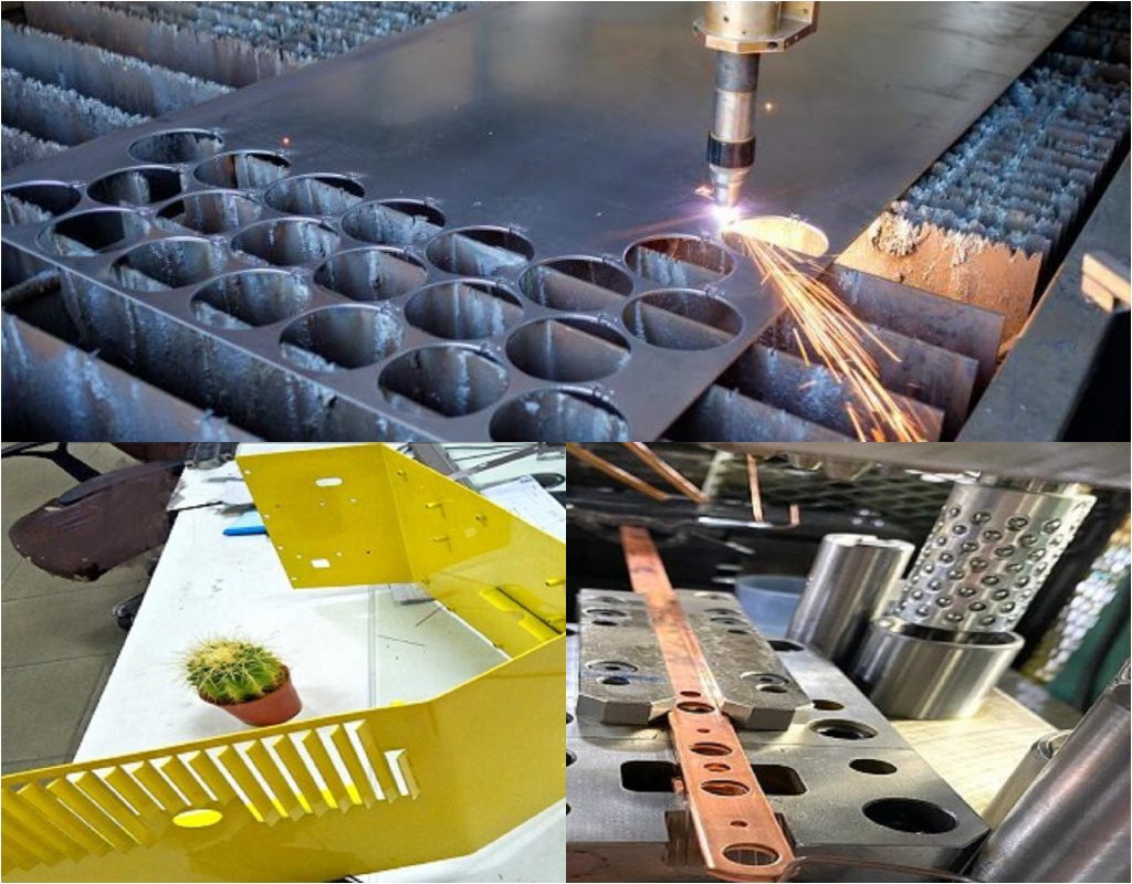
- Cutting: This is the starting point. We take a flat sheet and cut out the 2D profile of the part before it’s bent. We have options like laser cutting for complex shapes and tight tolerances, or shearing for simple straight cuts on large batches.
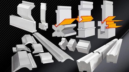
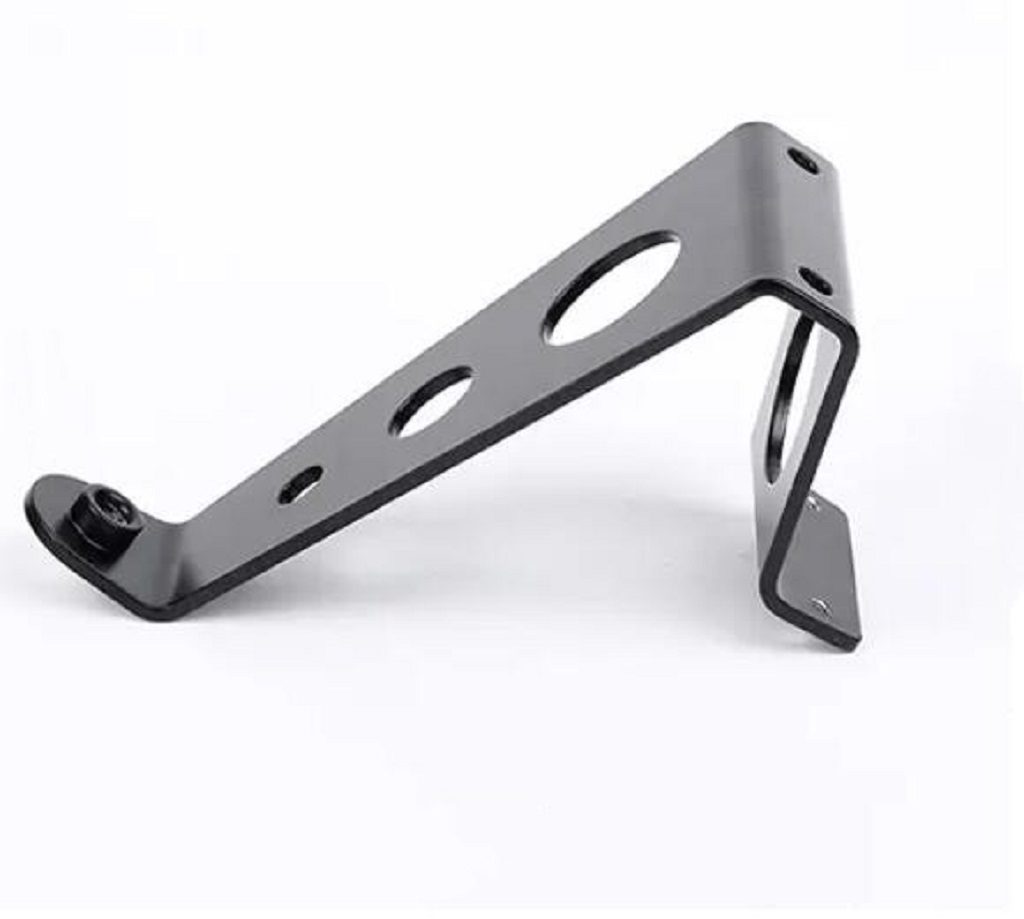
- Bending: This is how we turn a flat part into a box, bracket, or channel. Using a press brake, we apply force to create precise angles. The material, its thickness, and the bend radius are critical factors our engineers always double-check.
- Stamping: For high-volume parts with repeating features like louvers, logos, or shallow depressions, stamping is unbeatable. It uses a custom die to press the feature into the sheet metal very quickly.
Here’s a simple table to see how they compare:
| Method | Primary Use | Speed | Cost per Part (High Volume) | Best For... |
|---|---|---|---|---|
| Cutting | Creating the flat pattern | Varies | Medium | All parts, from prototype to production. |
| Bending | Forming 3D shapes/angles | Medium | Low | Enclosures, brackets, frames. |
| Stamping | Creating specific features | Very Fast | Very Low | High-volume parts with repeated designs. |
For many projects, we use all three. We might laser cut a blank, stamp a logo and some mounting dimples, and then bend it into its final shape. This is that "combination of punches" I mentioned, and orchestrating it is our specialty.
What is the 4T rule for sheet metal?
Have you ever designed a part with a sharp, 90-degree bend, only to find it cracked during production? This common design flaw stems from not understanding material limits.
The 4T rule is a guideline in sheet metal design stating that the minimum inside bend radius of a part should be four times the thickness of the material (4T). This helps prevent the material from cracking or failing at the bend line due to excessive stress.
Following design rules like this is crucial for manufacturability. While it's just a guideline, it’s a very safe starting point that helps us avoid costly and time-consuming problems down the line. When we receive a design, checking factors like the bend radius against material properties is one of the first things our engineers do.
Why This Rule of Thumb Matters
The 4T rule isn't an arbitrary number; it's based on the physics of how metal behaves. When you bend a sheet, the metal on the outside of the bend gets stretched (tension), and the metal on the inside gets compressed. If the bend is too sharp for the material's thickness, the outer surface can stretch beyond its limit and crack.
When Can You Bend the Rules?
The "4T" is a general recommendation, especially for harder materials like high-strength steels. However, it's not a universal law. Several factors can influence the minimum safe bend radius:
- Material Ductility: Softer, more ductile materials like certain aluminum or copper alloys can handle much tighter bends, sometimes as low as 1T or even a "sharp" bend with a minimal radius. Harder, less-ductile materials like titanium or certain stainless steels need a more generous radius.
- Grain Direction: Sheet metal has a grain direction from the rolling process. Bending parallel to the grain ("the hard way") is more likely to cause cracking than bending perpendicular to it ("the easy way"). Whenever possible, we orient parts on the sheet to bend against the grain.
- Tooling: The type of punch and die used in the press brake can also affect the outcome. A larger die opening can help distribute stress more evenly, allowing for a slightly tighter bend than a small opening.
What is the new technology in sheet metal?
Are your current suppliers using outdated equipment, leading to slower lead times and inconsistent quality? Falling behind on technology can mean falling behind your competition in the marketplace.
New technology in sheet metal is dominated by automation and data. This includes high-speed fiber lasers for cutting, robotic bending cells for automated forming, and integrated CAD/CAM software that streamlines the entire process from design file to finished part, ensuring speed and precision.

Embracing new technology is not just about having shiny new machines. It's about how that technology translates into real benefits for our customers. For someone like Mark, who needs reliable quality and on-time delivery, our investment in modern equipment is a direct answer to his biggest pain points.
The Impact of Modernization
A few years ago, we had a project for a customer in the electronics industry. They needed a complex enclosure with many small vents and precise bends. Their previous supplier struggled, delivering parts with warped surfaces from heat and inconsistent bend angles. This created huge delays in their assembly line.
We took on the project using our modern workflow:
- Fiber Laser Cutting: Unlike older CO2 lasers, our fiber laser cuts faster and with less heat input. This meant we could cut the intricate vent pattern without warping the thin stainless steel sheet. The precision was so high that every blank was identical.
- Automated Bending Cell: Instead of a human operator bending each part one by one, we programmed a robotic press brake. The robot handled the part, ensuring every single bend was at the exact same angle and location. This eliminated the human error and fatigue that caused inconsistencies.
- Integrated Software: Our engineer took the customer's 3D CAD file and our software automatically generated the flat pattern for the laser and the bending sequence for the robot. This seamless transition minimized programming time and prevented data entry errors.
What are the 7 sheet metal operations?
Do you find the terms used in sheet metal fabrication confusing? Not knowing the basic operations can make it difficult to communicate your design intent clearly with your manufacturer.
The seven primary sheet metal operations are cutting (separating material), bending (forming angles), drawing (stretching metal into a shape), punching (creating holes), and stamping (forming features with a die),compressing and shearing. These foundational processes can be combined to create almost any sheet metal part.
A Deeper Look at the Core Five
Understanding what each operation does helps you appreciate how a simple flat sheet becomes a complex functional part. Here’s a slightly more detailed breakdown:
- Cutting: This is always the first step. The goal is to create the flat, 2D outline of your part from a larger sheet. The main methods are laser cutting for precision and complex shapes, waterjet cutting for thick materials or those sensitive to heat, and shearing for fast, straight-line cuts.
- Bending: This operation gives the part its three-dimensional form. Using a machine called a press brake, we place the flat part over a V-shaped die and press down with a punch tool to create a bend. We can create simple 90-degree angles or much more complex multi-bend geometries.
- Drawing: This is a more advanced forming process used to make shapes like sinks, cans, or automotive body panels. We clamp a sheet metal blank over a die cavity and then press a punch into the sheet, forcing it to stretch and conform to the shape of the die. It requires careful engineering to prevent wrinkling or tearing.
- Punching: While laser cutting can make any shape of hole, punching is much faster and cheaper for standard shapes (circles, squares, slots) in high volumes. A machine called a turret punch press holds dozens of different shaped "punch and die" tools and can rapidly punch out a pattern of holes.
- Stamping: This is a broad term but often refers to using a stamping press and custom tooling to quickly form a feature. This can be as simple as pressing a company logo into a part (coining) or as complex as forming strengthening ribs and flanges in a single hit.
- Compressing: Processes like stamping, coining, and forging fall into this category. The primary force is compressive, squeezing the metal to conform to a die's shape. This is excellent for creating fine details and improving the surface hardness of the material.
- Shearing: This is the process of cutting metal by applying opposing forces that cause the material to fail along a specific line. Operations like punching, blanking, and shearing all rely on this fundamental process. A clean shear results in a smooth edge with minimal burr.
What is the rule of thumb for sheet metal?
When you're in the early stages of design, do you get stuck on small details? Having a few simple rules of thumb can help you make quick, effective decisions and keep your project moving forward.
A good general rule of thumb for sheet metal is the "K.I.S.S." principle: Keep It Simple, Stupid. This means designing parts with uniform wall thickness, generous bend radii, and standard hole sizes whenever possible to ensure manufacturability, lower costs, and faster production times.
I've seen thousands of designs over the years, and the most successful ones are often the simplest. Complicated designs introduce risk, increase cost, and extend lead times. By sticking to some basic principles, you can design parts that are robust and efficient to produce.
Practical Rules for Smart Design
While "Keep It Simple" is the overarching philosophy, here are a few more specific rules of thumb that our engineers at Worthy frequently share with clients to help them optimize their designs:
- Maintain Uniform Thickness: Design your entire part using a single, standard material thickness. Changing thickness within a part requires extra steps like welding or machining, which dramatically increases cost.
- Respect the Bend Radius: As we discussed with the 4T rule, always design bends with a radius equal to or greater than the material thickness. Trying to create perfectly sharp corners is a common mistake that leads to cracking.
- Space Features Apart: Keep holes and other features at least 2 to 3 times the material thickness away from any edge or bend line. Placing them too close can cause the material to bulge, deform, or tear during forming.
- Use Standard Tooling: Design holes, slots, and other cutouts to match standard punch sizes or common end mill diameters. Requiring custom tooling for a non-standard hole size adds unnecessary cost and delay.
- Design for Assembly: Think about how the part will be used. Can you add tabs and slots to make alignment easier? Can you combine multiple parts into a single, more intelligently bent component to reduce welding and assembly time?
How thick can sheet metal be before it's considered a plate?
Does the terminology between "sheet" and "plate" matter? Yes, it does, because it dictates the type of machinery, processes, and costs involved in manufacturing your part.
While there's no single universal standard, the general dividing line is around 6 mm (or roughly 1/4 inch). Material thinner than 6 mm is typically called "sheet metal," while material thicker than 6 mm is referred to as "plate."
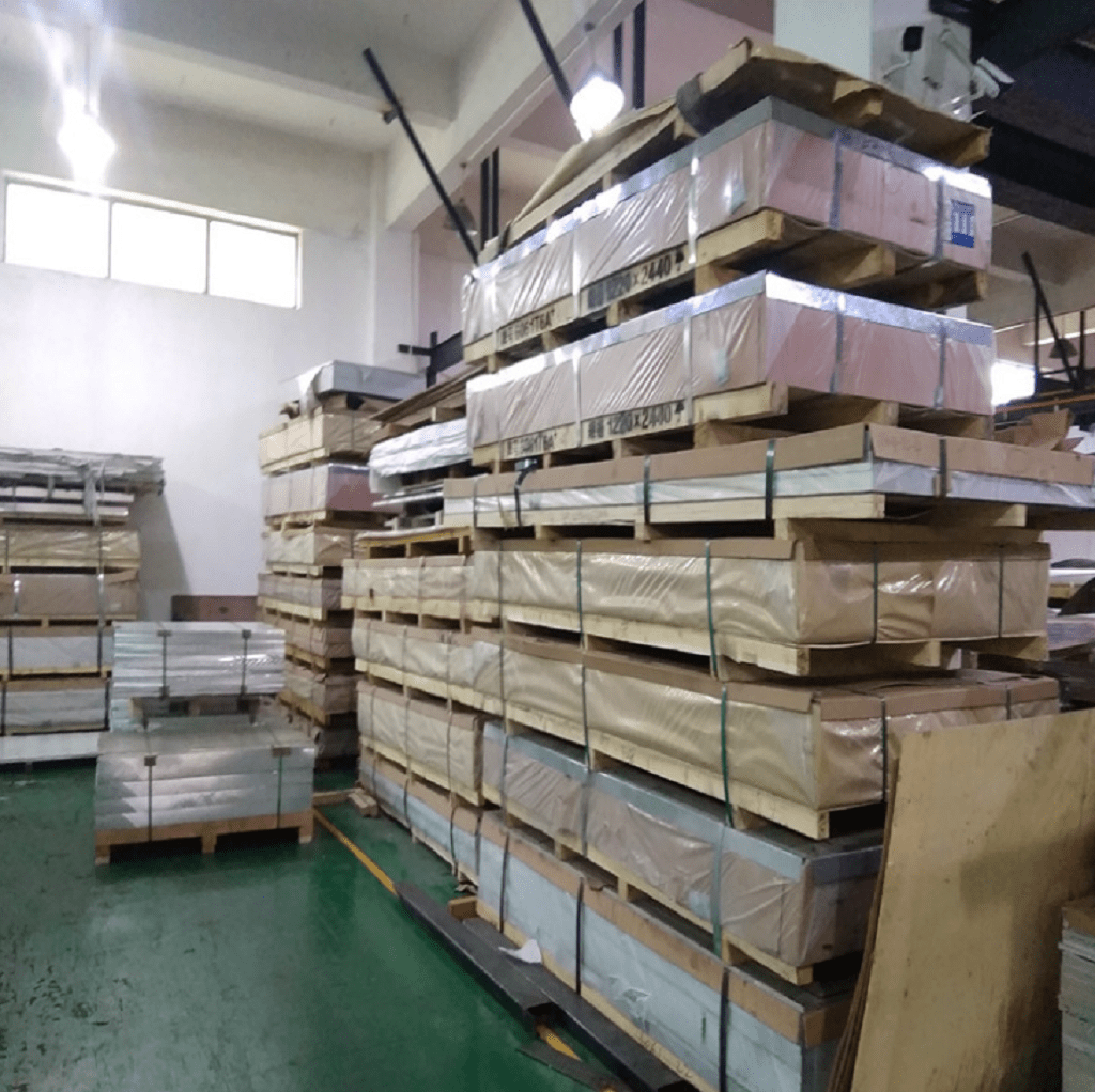
This distinction is important because the tools and techniques used to work with sheet and plate are very different. At Worthy, we specialize in sheet metal fabrication, using press brakes and turret punches. Working with thick plate requires much heavier-duty equipment, like industrial saws and high-tonnage forming presses.
Why the Distinction Matters
The difference between sheet and plate goes beyond a simple number. It fundamentally changes the manufacturing approach, influencing cost, speed, and capabilities.
| Feature | Sheet Metal (< 6mm) | Plate Metal (> 6mm) |
|---|---|---|
| Handling | Can often be handled by one person or light equipment. | Requires cranes, forklifts, or other heavy machinery. |
| Cutting | Laser cutting, punching, and shearing are common. | Plasma cutting, waterjet, or flame cutting are preferred. |
| Forming | Formed on press brakes. | Requires immense force; often "hot formed" or rolled. |
| Primary Use | Enclosures, brackets, chassis, consumer products. | Structural frames, ship hulls, bridge components, molds. |
| Precision | Tolerances are typically tighter, measured in +/- 0.1mm. | Tolerances are looser, often measured in whole millimeters. |
What is the minimum distance between holes in sheet metal?
Have you ever seen a part where the metal between two holes is warped or torn? This common defect is caused by placing features too close together, creating a weak point in the material.
A safe rule of thumb is to maintain a minimum distance of at least twice the material thickness (2T) between the edges of any two holes. For holes near an edge or a bend, this distance should be increased to at least 2.5T or 3T.
This isn't just an arbitrary suggestion; it's a critical design-for-manufacturability (DFM) guideline that prevents material failure. When a hole is punched or drilled, it puts stress on the surrounding metal. If another feature is too close, these stress zones overlap, leading to deformation and weakness.
The Engineering Behind the Rule
When we create a hole, we are displacing and shearing material. This process has a physical impact on the area immediately around the hole. Ignoring this can lead to several problems that compromise the quality and strength of your part.
Key Spacing Guidelines:
- Hole-to-Hole Distance: The material between two holes is often called the "web" or "land." Making this web too thin (less than 2T) is risky. During punching, the force of the second punch can deform the first hole or cause the web to tear.
- Hole-to-Edge Distance: The distance from the edge of a hole to the edge of the part should also be at least 2T, and ideally 3T. Placing a hole too close to the edge can cause the edge to bulge outwards, ruining the part's dimensional accuracy.
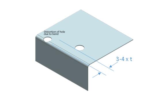
- Hole-to-Bend Distance: This is one of the most critical rules. A hole placed too close to a bend line will be stretched and deformed into a teardrop or oval shape when the part is bent. The minimum distance from the edge of the hole to the start of the bend line should be at least 2.5 times the material thickness plus the bend radius.
What are the four methods of processing metals?
Looking at the big picture, where does sheet metal fabrication fit in? Understanding the main categories of metal processing helps you see why we choose specific methods for specific jobs.
The four main methods of processing metals are casting (pouring liquid metal into a mold), forming (shaping solid metal without removing material), machining (cutting material away), and joining (assembling separate pieces, like welding). Sheet metal fabrication is a sub-category of forming.
The Four Pillars of Metalworking
Thinking in these four categories helps clarify why you might choose sheet metal for your part instead of, say, 3D printing or casting. It all comes down to the desired shape, quantity, strength, and cost.
-
Casting: This is one of the oldest methods. You melt metal and pour it into a mold to create a complex, solid shape.
- Pros: Excellent for intricate, three-dimensional shapes (like statues or engine blocks). Can produce parts in high volume relatively cheaply once the mold is made.
- Cons: Molds can be very expensive to create. The surface finish is often rough, and tolerances are not as tight as other methods.
-
Forming: This is our world. It involves shaping solid metal using force. This includes sheet metal bending, forging (hammering hot metal), and extrusion (pushing metal through a shaped die, like making a pipe).
- Pros: Creates strong, lightweight parts. Very fast and cost-effective for both low and high volumes. Minimal material waste.
- Cons: Limited to forms that can be made from a sheet or block.
-
Machining (Subtractive Manufacturing): This involves cutting away material from a solid block to achieve the desired shape. Think of it like sculpting from stone. Common methods include milling, turning (on a lathe), and drilling.
- Pros: Can achieve extremely tight tolerances and excellent surface finishes. Great for complex geometries that can't be formed.
- Cons: Can be slow and produces a lot of waste material. Often more expensive per part than forming.
-
Joining: This category covers all the ways we assemble parts. Welding is the most common, but we also use riveting, brazing, and adhesive bonding.
- Pros: Allows for the creation of large, complex assemblies from simpler components.
- Cons: The joint can sometimes be a weak point if not done correctly. It's an additional process that adds time and cost.
Conclusion
In short, understanding the core forming techniques is just the start. The true art lies in combining them smartly to create high-quality, cost-effective parts for your specific project.