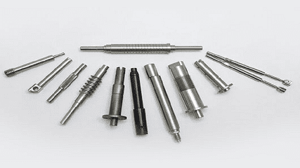
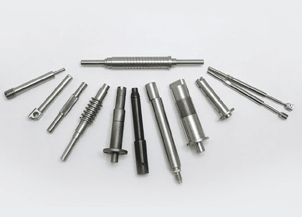
Methods of Machining Shafts Outer Cylindrical Surface
Getting a perfect finish on shafts is tough. The wrong method leads to waste and delays. Understanding the right process is key to getting it right every time.
The primary methods for machining a shaft's outer cylindrical surface are turning and grinding. Turning is used for initial shaping and roughing, while grinding is used for achieving high precision and a very fine surface finish. The choice depends on the required tolerance and final application.
The outer circle is the main surface of the shaft part, so to make a reasonable machining process of the shaft part, we should first understand the various machining methods and machining schemes of the outer circle surface.
一 What is Characteristics and Applications of CNC Turning
CNC Turning is one of the primary machining methods for cylindrical surfaces. Its key characteristic lies in requiring the positioning datum of the workpiece's cylindrical surface to be coaxial with the lathe spindle's rotational axis. This fundamental principle allows turning to be universally applicable for machining cylindrical surfaces on various workpieces through appropriate adjustments.
The process is versatile, capable of processing both non-ferrous and ferrous metals, with particular excellence in non-ferrous metal machining. Turning serves dual purposes as both roughing and finishing operations. Generally, cylindrical surfaces on shaft components require structural considerations due to their inherent design characteristics.
Due to (L≥ D), most of them are machined on horizontal lathes, so turning is one of the most widely used methods of machining rotating surfaces, its characteristics are as follows:
(1) The wide range of applications
Turning can process various surfaces including internal and external cylindrical surfaces, conical surfaces, end faces, grooving, cutting, thread cutting, center boring, drilling, reaming, boring, spring winding, and other tasks. When equipped with specific attachments and fixtures, lathes can also perform boring, grinding, polishing, and other operations.
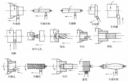
Figure 61-2 Basic content of turning processing
(2)High productivity.
During turning, the machining process is continuous cutting, there is basically no impact phenomenon, the length of the hanging of the tool bar is very short, high rigidity, so it can be used to high cutting amount, so the productivity of turning is very high.
(3) Wide precision range.
On horizontal lathes, rough turning of castings and forgings can achieve economical machining accuracy IT11-IT13 with Rα reaching 12.5-50 μm; finish turning can achieve economical machining accuracy IT7-IT8 with Rα reaching 0.8-1.6 μm. On high-precision lathes, using tungsten-titanium-cobalt carbide hard alloys and cubic boron nitride blades, combined with high cutting speeds (160m/min or higher), shallow depth of cut (0.03-0.05mm), and small feed rates (0.02-0.2mm/r) for precision turning, can achieve very high accuracy and minimal surface roughness. Large precision external cylindrical surfaces are commonly processed by precision turning instead of grinding.
Numerical Control (NC) lathes enable the machining of complex surface components that are difficult or impossible to process on conventional horizontal lathes. These machines deliver exceptional precision and ensure consistent product quality. Compared to traditional horizontal lathes, NC lathes can boost productivity by 2-3 times, with particularly complex parts achieving productivity gains of 10-20 times or even higher. This technological advancement significantly reduces the physical strain on workers during manufacturing processes.
(4) High-speed precision turning of non-ferrous metals
Using diamond tools on high-precision lathes, the dimensional tolerance grade IT6 to IT5 can be achieved, with surface roughness Rα reaching 1.0 to 0.1 μm, and even achieving a mirror finish.
(5) Low production cost.
The structure of the lathe tool is simple, the grinding and installation are very convenient, many lathe fixtures have been standardized production as accessories, it can meet the requirements of a certain machining accuracy, short production preparation time, low machining cost.
二 What is the Grinding ?
Grinding is the process of grinding a workpiece on a grinding machine with a grinding wheel or other grinding tool. There are many kinds of grinding machines, the most common of which are: external round grinding machine, internal round grinding machine and flat grinding machine.
As a cutting tool, the grinding wheel is a porous object made of abrasive and binder by sintering method. Due to the differences in abrasive, binder and manufacturing process, the characteristics of the grinding wheel include abrasive, grain size, hardness, binder, structure, shape and size.
Grinding of grinding wheel is a combination of three actions: cutting, engraving and sliding.
(一) What is the characteristics of Grinding Process?
(1) High precision with minimal surface roughness.
During grinding, the grinding wheel features numerous cutting edges with a radius of curvature P≈0.006–0.012 mm, significantly smaller than the P≈0.012–0.032 mm of conventional turning and milling tools. These razor-sharp cutting edges can remove metal layers as thin as a few micrometers, a critical requirement for precision machining. While conventional cutting tools can achieve smaller radii of curvature, their durability is insufficient to enable cost-effective, stable precision processing.
The grinding machine used for grinding has higher precision than the general cutting machine tool, good rigidity, good stability, and has a micro feed mechanism to control the small cutting depth, so as to carry out micro cutting, so as to ensure the realization of precision machining.
During grinding, the cutting speed is extremely high. For example, the cutting speed for standard cylindrical grinding is "c ≈ 30-35 m/s, while high-speed grinding requires" c> 50 m/s. When abrasive particles move at such high speeds across the workpiece surface, multiple cutting edges simultaneously perform the grinding process. Each abrasive edge removes only a minimal amount of metal, resulting in a thin residual layer that facilitates the formation of a smooth surface.
Therefore, grinding can achieve high precision and low roughness. Generally, the grinding accuracy can reach IT7 ~ IT6. The roughness Rα is 0.2 ~ 0.8 μm, and when small roughness grinding is used, the roughness Rα can reach 0.008 ~ 0.1 μm.
(2) Sand wheels possess self-sharpening properties.
Unlike other cutting tools, sand wheels maintain their cutting edge through natural sharpening during grinding. When conventional tools develop dulled or damaged edges, they require replacement or regrinding. However, sand wheels' inherent self-sharpening capability allows abrasive grains to continuously perform cutting with sharp edges. In industrial applications, this principle is utilized for intensive continuous grinding to enhance production efficiency in machining processes.
(3) Capable of grinding highly hard materials.
The abrasive grains in grinding wheels possess exceptional hardness and heat resistance, enabling them to process not only standard materials like unquenched steel, cast iron, and non-ferrous metals, but also challenging materials that other tools struggle with or cannot handle, such as quenched steel and cemented carbides.
(4) High grinding temperature.
During the grinding process, intense external friction occurs between the grinding wheel and workpiece due to its high-speed rotation. Simultaneously, abrasive particles compress the workpiece surface, causing elastic and plastic deformation that generates significant internal friction within the material. This combined action of external and internal friction produces substantial grinding heat.
Due to the grinding wheel's poor thermal conductivity, the massive heat generated in the grinding zone cannot dissipate quickly enough, resulting in instantaneous temperatures reaching 800-1000°C conditions that can even melt metal particles. Consequently, workpiece surfaces are prone to burn damage, while quenched workpieces are more susceptible to annealing during grinding, leading to reduced surface hardness.
For materials with poor thermal conductivity, under the action of high temperature grinding, it is easy to produce a large temperature difference between the inner surface and the surface of the workpiece, resulting in a large grinding stress and strain on the surface of the workpiece, and sometimes it will cause very fine cracks on the surface of the workpiece, reducing the surface quality. In addition, the workpiece material softened at high temperature is easy to block the grinding wheel, which not only affects the service life of the grinding wheel, but also affects the surface quality of the workpiece.
Therefore, during grinding operations, a substantial amount of cutting fluid should be utilized. The application of cutting fluid not only serves cooling and lubrication purposes but also helps flush the grinding wheel. By removing fine chips and fragmented abrasive particles, the cutting fluid prevents wheel clogging, thereby effectively improving workpiece surface quality and extending the grinding wheel's service life.
When grinding steel parts, the widely used cutting fluid is soda water or emulsion. When grinding cast iron, bronze and other brittle materials, cutting fluid is generally not added, but the dust is removed by vacuum cleaner.
(二) Advantages of grinding technology
In recent years, grinding is developing towards high precision, small roughness and high efficiency.
(1) High-precision, low-roughness grinding.
This includes precision grinding (Rα 0.1 to 0.05 μm), super-precision grinding (Rα 0.025 to 0.012 μm), and mirror-polished grinding (Rα 0.006 μm). These methods can replace grinding operations, reducing labor intensity and improving productivity.
When performing low-roughness grinding, in addition to specific requirements for the grinding machine, the grinding wheel must undergo precision dressing to ensure its abrasive grains maintain micro-sharpness and uniform micro-sharpness distribution. During operation, the micro-sharp edges of the abrasive grains cut fine chips from the workpiece surface. Simultaneously, under appropriate grinding pressure, the friction polishing effect generated between the semi-dull micro-sharp edges and the workpiece surface achieves high precision and minimal surface roughness.
(2) High efficiency grinding.
High efficiency grinding includes high speed grinding and strong grinding, the main purpose of which is to improve productivity.
High-speed grinding is a grinding method that uses high grinding speed (vc> 50m/S) and corresponding increase in feed to improve productivity. High-speed grinding can also improve the machining accuracy of the workpiece and reduce the surface roughness, and the service life of the grinding wheel can also be improved.
Hard grinding is a grinding method with a large cutting depth (up to 10mm) and slow axial feed (0.01 ~ 0.3m/min). It can directly grind the required surface shape and size of parts on cast and forged blanks, thus greatly improving production efficiency.
(三) How to make outer cylindrical surface on a non-centering cylindrical grinder
The working principle of the non-center-type cylindrical grinding machine is illustrated in Figure 6-1-3. Unlike conventional universal cylindrical grinders, this machine positions workpieces between the grinding wheel and guide wheel instead of using centers or chucks. The workpiece is supported by a lifting plate, with its outer circumference serving as the positioning reference. Both the grinding wheel and guide wheel rotate in the same direction. The guide wheel, made of corundum sand bonded with resin or rubber (high-friction material), rotates at speed n. While the workpiece would theoretically rotate at the same linear speed as the grinding wheel, friction from the guide wheel restricts this motion, causing the workpiece to rotate at a speed approaching that of the guide wheel (which is significantly lower than the grinding wheel's). This creates a substantial speed differential between the grinding wheel and workpiece, generating the grinding effect. By adjusting the guide wheel's rotational speed, the workpiece's circumferential feed rate can be precisely controlled.
During non-center grinding operations, the workpiece center must be positioned higher than the centerline connecting the guide wheel and grinding wheel. This configuration ensures that contact points between the workpiece, grinding wheel, and guide wheel are not aligned along the same diameter, allowing specific protruding surfaces to gradually become rounded through repeated rotations. This method prevents the formation of angular workpieces (see Figure 6-1-4). Practical experience shows that a higher workpiece center facilitates better roundness and accelerates the grinding process. However, the elevation should not exceed 0.15-0.25 times the workpiece diameter (d), as excessive vertical lift from the guide wheel may induce workpiece vibration, compromising surface finish quality. The optimal clearance is typically maintained at this range.
The external cylindrical grinding machine employs two grinding methods (see Figure 6-1-5): longitudinal grinding and transverse grinding. The longitudinal method is ideal for cylindrical workpieces without bosses, allowing the grinding surface length to exceed or fall below the grinding wheel width. This process enables continuous piece-by-piece grinding, achieving high productivity. The transverse method is particularly suitable for workpieces with stepped surfaces or for forming rotary body surfaces, though it...
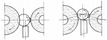
Figure 6-1-4 Schematic diagram of non-central cylindrical grinding
The length of the surface to be shaved cannot exceed the width of the grinding wheel.
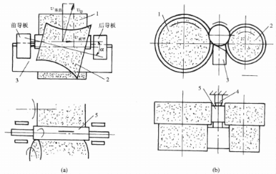
Figure 6-1-5 Schematic diagram of non-central cylindrical grinding method
(a) longitudinal grinding method; (b) transverse grinding method
1-Grinding wheel 2-Guide wheel 3-Support plate 4-Stop block 5-Workpiece
When performing external cylindrical grinding on a centerless grinder, workpieces don't require center boring. This setup saves time and effort in clamping while enabling continuous grinding. With guide wheels and support plates maintaining the workpiece throughout the process, even low-stiffness workpieces can be processed using larger cutting parameters. Consequently, centerless external cylindrical grinding demonstrates higher productivity.
Since the workpiece positioning reference is the milled surface itself rather than the center hole, this eliminates errors caused by center hole inaccuracies, misalignment between the worktable's motion direction and the front-back centerline, as well as radial runout of the center. The size accuracy of workpieces milled without centers ranges from IT7 to IT6, with a roundness error of 0.005mm, cylindrical error of 0.004mm/100mm length, and surface roughness Rα value not exceeding 1.6μm. When equipped with appropriate automatic loading/unloading mechanisms, centerless cylindrical grinding can be easily automated. However, due to the time-consuming setup process of centerless grinders, they are only suitable for mass production. Additionally, their limitations in workpiece support and transmission mechanisms restrict them to processing smaller-sized, simpler-shaped workpieces. Furthermore, centerless cylindrical grinders are not recommended for workpieces with discontinuous outer surfaces (e.g., long keyways) or those requiring high coaxiality between inner and outer surfaces.
(四) Common defects and Solutions of external cylindrical grinding
In the grinding process, due to the influence of various factors, the surface of parts is prone to various defects. The analysis of common defects and solutions is as follows:
(1) Polygonal marks.
The surface of the workpiece displays evenly spaced linear traces along the generatrix direction, with a depth of less than 0.5 μm (as shown in Figure 6-1-6). This phenomenon primarily results from periodic radial vibrations between the grinding wheel and workpiece, caused by factors such as unbalanced grinding wheels or motors, insufficient bearing rigidity or excessive clearance, poor contact between the workpiece center hole and center punch, or uneven grinding wheel wear. Multiple vibration mitigation measures can be implemented, including meticulous balancing of grinding wheels and motors, optimizing contact between center holes and center punches, timely grinding wheel dressing, and proper adjustment of bearing clearance.
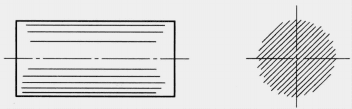
Figure 6-1-6 Polygonal defect
(2) Spiral pattern.
The milled workpiece surface displays a deep spiral pattern, with the spacing between marks equal to the workpiece's rotation cycle.
The longitudinal feed rate is illustrated in Figure 6-1-7. This issue primarily arises from two causes: uneven micro-edge height on the grinding wheel or localized contact between the wheel and workpiece (e.g., when the grinding wheel's contour line is not parallel to the workpiece's contour line), as well as uneven rigidity of the headstock and tailstock, or poor spindle rigidity. Multiple measures can address and prevent this problem: 1) Correct the grinding wheel to maintain uniform micro-edge height; 2) Adjust bearing clearance to ensure spindle positioning accuracy; 3) Modify both sides of the grinding wheel into shoulder-shaped or chamfered edges to prevent end cutting; 4) Use appropriate lubricant for the worktable and incorporate an unloading mechanism; 5) Implement low-pressure lubrication for guide rails.
(3) Surface roughening (scratches or scratches).
Common surface roughening phenomena on workpieces are shown in Figure 6-1. As shown in Figure 8, the primary causes of pitting include excessive grain self-sharpening, unclean cutting fluid, and abrasive chips accumulating on the grinding wheel cover between the wheel and workpiece. To eliminate pitting, implement the following measures: select a slightly harder grinding wheel, clean the wheel after dressing with cutting fluid and a brush, filter the cutting fluid, and remove abrasive chips from the grinding wheel cover.
(4) Burn marks.
These can be categorized into spiral and spot burn marks, as illustrated in Figure 6-1-9. The primary cause of burn marks is the high-temperature effect during grinding, which alters the surface microstructure of the workpiece, resulting in significant changes to its surface hardness. To eliminate burn marks, measures include reducing the grinding wheel's hardness, decreasing grinding depth, appropriately increasing the workpiece's rotational speed, and minimizing the contact between the grinding wheel and the workpiece.
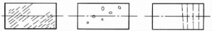
Figure 6-1-8 Scratch (Scratch or scratch) defect
Contact area, timely correction of the grinding wheel, sufficient cooling, etc.

Figure 6-1-9 Burn Defect
三 Precision Machining of outer cylindrical surface
Precision machining refers to a manufacturing process that achieves high levels of processing accuracy and surface quality during specific development stages. Currently, it denotes techniques where components exhibit machining precision of 1 to 0.1 μm and surface roughness Rα values ranging from 0.1 to 0.008 μm, primarily involving grinding, honing, super-finishing, and polishing. In a broader context, it also encompasses scraping, wide-tooth fine planing, and diamond tool cutting. For external cylindrical surfaces, the main precision machining methods include grinding, super-finishing, and polishing.
1. Grinding
Grinding is a precision machining technique that removes an extremely thin surface layer from workpieces using grinding tools and abrasives. Common types include flat grinding, external cylindrical grinding, internal cylindrical grinding, and thread grinding. This process achieves IT5 precision, with surface roughness Rα values as low as 0.1–0.01 μm and a grinding allowance of approximately 0.005–0.02 mm. As the most widely used optical finishing method, grinding ensures high surface quality through controlled material removal.
(1) Grinding Principle.
During the grinding process, abrasive material is applied between the grinding tool and the workpiece's surface. The tool, made of a softer material than the workpiece, performs complex relative motion under specific pressure. Abrasive particles embedded in the grinding material perform micro-cutting on the already precision-machined workpiece surface during this motion, removing extremely thin metal layers (approximately 0.01 to 0.1 μm).
Additionally, chemical reactions occur during grinding: abrasive particles form a thin oxide film on the workpiece surface. These raised oxide layers are continuously scraped away by abrasive grains, forming new oxide layers that are then scraped off again. This repetitive process, combined with complex and non-repetitive motion trajectories, ensures uniform surface processing. As uneven protrusions are progressively removed, the surface roughness gradually decreases.
(2) Grinding method.
There are two methods of grinding, manual grinding and mechanical grinding.
① Manual Grinding: When grinding the outer diameter, the workpiece is clamped in the lathe chuck or supported by a center, rotating at low speed. The grinding tool is mounted on the workpiece, with grinding material applied between the tool and workpiece. The grinding tool is then manually pushed to perform reciprocating motion. The outer diameter grinding tool is shown in Figure 6. As shown in Figures 6-10(a) and 6-10(b), the coarse grinding sleeve features an oil groove for grinding agent storage, while the fine grinding sleeve lacks this feature. The reciprocating speed of the grinding tool is typically recommended to be 20-70 m/min.
Figure 6-1-10: External cylindrical grinding tools (a) Coarse grinding tool; (b) Fine grinding tool
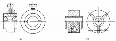
Figure 6-1-10: External cylindrical grinding tools (a) Coarse grinding tool; (b) Fine grinding tool
② Mechanical grinding: The grinding equipment is specifically designed for particular workpieces, featuring high production efficiency and ideal for mass production. As shown in Figure 6-1-11, this is a planetary transmission-type double-sided grinding machine.
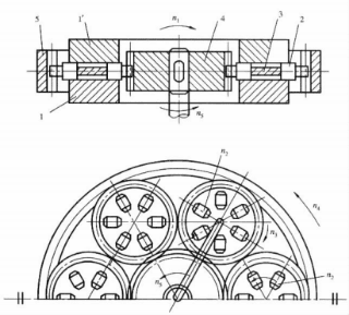
Figure 6-1-11 Planetary gear grinder 1, -Upper grinding disc 1-Lower grinding disc 2-Workpiece 3-Workpiece chuck 4-Internal gear ring 5-Center drive gear n1-grinding wheel speed n2-workpiece speed n3-Workpiece chuck speed n4-Internal gear ring speed n5-Center drive gear speed
The central gear 5 drives six workpieces 2 and six clamping discs 3, where each clamping disc 3 functions as a planetary gear during transmission. These six planetary gears mesh with a central internal gear 4. The planetary gears rotate both on their own axes at speed n3 and orbit around the central gear. The grinding disc rotates at speed n1. The workpieces are positioned in slots of the planetary gears (i.e., workpiece clamps) and move relative to both the planetary gears and the grinding disc.
In addition, machine grinding can not only grind the outer cylindrical surface, but also suitable for the inner cylindrical surface, plane, spherical surface, hemispherical surface and other surface grinding.
(3) Sand-embedded and sand-free grinding.
Depending on whether abrasive particles are embedded in the grinding tool, the process is classified as either sand-embedded or sand-free grinding.
① Sandblasting: The abrasive material is softer than the workpiece, with uniform structure, low deformation, and no surface spots. Common materials include gray cast iron, copper, aluminum, and soft steel. In the process, the abrasive is directly added to the working area, and the abrasive particles are automatically embedded in the grinding tool under compression, which is called automatic sand embedding; The abrasive is directly pressed into the surface of the grinding tool before processing, which is called forced sanding. This method is mainly used for the grinding of precision measuring tools.
Grinding tools are typically made from materials softer than the workpiece material, with common options including cast iron, bronze, and low-carbon steel. The grinding system consists of abrasives and grinding fluid. Common abrasives are alumina (Al₂O₃) and silicon carbide. For coarse grinding, abrasives range from 240# to W14, while precision grinding requires W14 to W5 abrasives. Standard grinding fluids include kerosene, engine oil, and vegetable oils. To facilitate oxide film formation on the workpiece surface during grinding and shorten the process, appropriate amounts of oleic acid or grinding grease are added to activate the abrasive action.
②No sandblasting: The abrasive material is relatively hard, while the abrasive grains are softer (e.g., chromium oxide). During the grinding process, the abrasive grains remain free. The grinding tool remains free of surface impregnation. Common materials include hardened steel and mirror-polished glass.
(4) Grinding Materials and Grinding Agents.
Grinding tools are typically made from materials softer than the workpiece material, with common options including cast iron, bronze, and low-carbon steel. The grinding system consists of abrasives and grinding fluid. Common abrasives are alumina (Al₂O₃) and silicon carbide. For coarse grinding, abrasives range from 240# to W14, while precision grinding requires W14 to W5 abrasives. Standard grinding fluids include kerosene, engine oil, and vegetable oils. To facilitate oxide film formation on the workpiece surface during grinding and shorten the process, appropriate amounts of oleic acid or grinding grease are added to activate the abrasive action.
2. Ultra-finishing
Superfinishing is a precision machining method that uses ultra-fine abrasive oilstones to perform micro-cutting on workpieces under constant pressure (5 ~ 20Mpa) and complex relative motion, with the main purpose of reducing surface roughness.
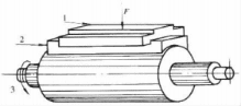
Figure 6-1-12 Ultra-finishing
The ultra-precision machining of external cylindrical surfaces is illustrated in Figure 6-1-12. The workpiece rotates at a low speed (3), while the grinding stone simultaneously performs reciprocating vibrations (1) at 12-25Hz with 1-3mm amplitude and longitudinal feed movement (2) at 0.1-0.15mm/r. The grinding stone's pressure on the workpiece surface is regulated by adjusting the pressure spring. A cutting fluid with specific viscosity is injected between the grinding stone and workpiece to remove chips and form an oil film. During machining, each abrasive grain on the grinding stone creates extremely fine, non-repetitive crosshatched marks on the workpiece surface, removing microscopic protrusions. As these protrusions gradually diminish, the contact area between the grinding stone and workpiece increases, reducing pressure and consequently weakening the cutting action. When the pressure falls below the oil film's surface tension, the grinding stone separates from the workpiece, automatically halting the cutting process.
Supersmooth machining can only remove microscopic peaks, typically leaving no or minimal machining allowance (usually 0.003 to 0.01 mm). After this process, the Rα value can reach 0.1 to 0.01 μm, significantly increasing the actual contact area between mating surfaces of components. However, this technique generally cannot improve dimensional accuracy, form accuracy, or positional accuracy, which must be ensured by preceding processes. Supersmooth machining boasts high productivity and is commonly used in mass production for machining external cylindrical surfaces of crankshafts and camshafts, end planes of flywheels and clutches, as well as raceways of rolling bearings.
3. Polishing
Polishing operations are performed on high-speed rotating polishing wheels. These processes can only reduce surface roughness, but cannot improve dimensional and form/shape accuracy, nor maintain the machining precision achieved before polishing. The primary functions of polishing include: eliminating surface machining marks, enhancing part fatigue strength, serving as surface finishing, and ensuring quality for electroplated components through pre-plating polishing. Notably, none of these purposes are aimed at improving machining accuracy.
Polishing wheels are typically made of materials such as felt, rubber, leather, or fabric, offering elasticity to polish various surfaces. The polishing fluid (grinding paste) is formulated with alumina, iron oxide, abrasives, oleic acid, and soft fats. During polishing, this paste is applied to the wheel. The workpiece is pressed against the wheel, and under the action of the grinding paste, a thin, soft film forms on the metal surface through chemical reactions. This film can be removed by the abrasive material without leaving marks. Additionally, the high polishing speed generates intense friction, causing the workpiece surface to reach high temperatures. This thermal effect induces plastic flow in the surface layer, filling in surface dents and reducing surface roughness.
4. Roll forming
Rolling is a machining process that applies pressure to metal workpieces using rolling tools, inducing plastic deformation to reduce surface roughness and enhance surface properties. This is a non-cutting process. Figure 6-1-13 shows a schematic diagram of rolling machining.
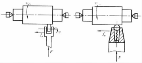
Figure 6-1-13 Schematic diagram of rolling processing
(a) Roll press; (b) Ball press
(a) Roll press; (b) Ball press
Rolling machining has the following characteristics:
(1) Before rolling, the surface roughness Rα value of the workpiece should not be greater than 5μm, the surface should be clean, and the diameter allowance should be 0.02 ~ 0.03mm.
(2) The shape accuracy and position accuracy of rolling depend mainly on the previous process.
(3) The material of the rolled workpiece is generally plastic, and the material structure should be uniform. Cast iron parts are generally not suitable for rolling.
(4) High productivity of rolling process
Conclusion
The best method for machining shafts—turning, grinding, or a combination—depends entirely on your required precision and finish. Understanding these processes ensures you get the right quality for your application.